• 27 •
2%
2%
1 m.
1 m.
1 m.
1 m.
Installation Manual • COMPACTAIR ADV IOM-MIL157E-0418
2.- INSTALLATION
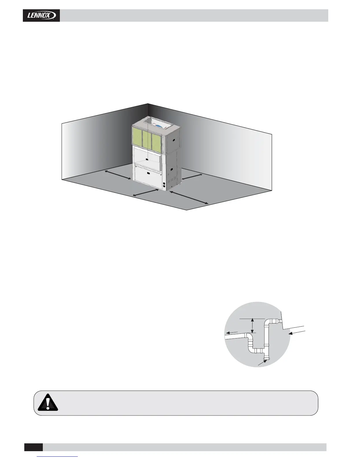
2.5.- INSTALLATION CLEARANCES.
Clearance around the unit for service and maintenance.
SERVICE SPACE
Space should be left free for access or servicing, to ease the installation of ducts, drainage connections, electric installation and
cleaning fi lters, as well as easy access to the unit.
2.6.- DRAINS.
All the outdoor and indoor sections of these units have a 3/4” steel threaded drain pipe welded to the condensation tray.
The units which have a double circuit (060/075/085) have two drain pipes, one on each side and both have to be connected.
Drainage pipes will be fi tted for each tray through a siphon with a height difference
of 80 mm. to avoid drainage problems from the depression formed by the fans.
The pipes should have an inclination of 2% to ease drainage of condensation.
Also slightly tip the unit toward the drainage side. Check that the
condensation trays are clean and free from dirt and other debris from the works
and that water drains correctly.
The drains must be independents, no connect the condenser drain with the
evaporator drain
Mín. 80 mm.
Inspection and cleaning stopper
LOCATION
Install air entry and exit ducts should be fi tted. The unit should be assembled on bases previously made and stood on absorbent and
antivibrating material to avoid the vibrations being transmitted to the structure of the building.
Place the anti-vibration to avoid any buckling.
To assure proper water evacuation in the base of the unit to avoid overfl ow or ice accumulation
 Loading...
