SET POINT THERMOSTAT FUNCTION DESCRIPTION
9
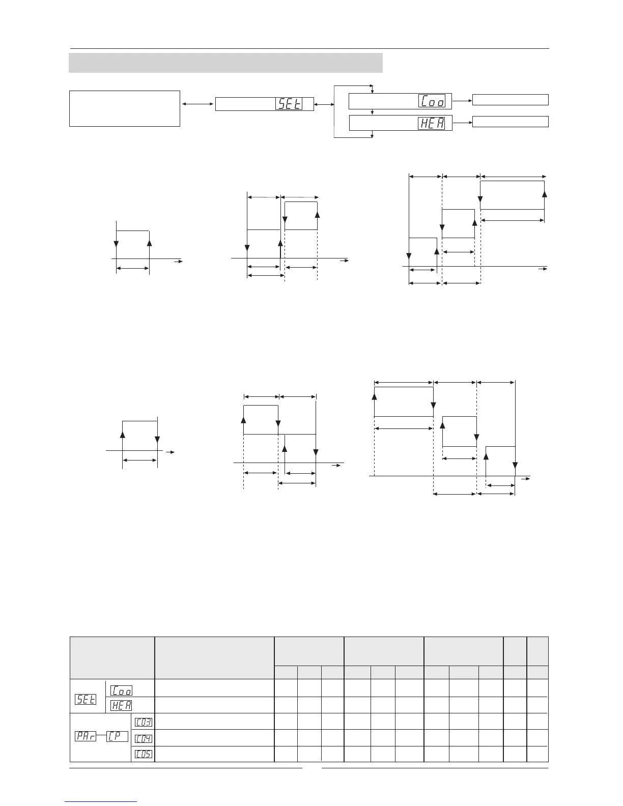
COOLING OPERATING MODE
Operation with one compressor is as shown in the diagram taking into account that the temperature about which
the controller takes over is the inlet water temperature. When this temperature exceeds the set point + tolerance
range (differential) the compressor starts to produce cool water. When inlet water temperature gets below the set
point the compressor stops. For example, when the set point = 11ºC and differential = 2ºC, the compressor stops
when inlet water temperature is 11ºC and starts when this temperature exceeds 13ºC.
Operation with one compressor is as shown in the diagram taking into account that the temperature about which
the controller takes over is also the inlet water temperature. When this temperature gets below the set point -
Differential, the compressor starts to produce heat water. When the inlet water temperature exceeds the set point,
the compressor stops. For example: when the set point = 41ºC and differential = 2ºC, the compressor stops when
the inlet water temperature is 41ºC and starts when this temperature gets below 39ºC.
ºC
Compressor
ON
Compressor
OFF
Set point + DifferentialSet point
c03
Set point
c03
c05
Step 1
c03
Step 2
ºC
Set point
c03
c05
ºC
c03
c05
2xc03
Step 1 Step 3Step 2
Set point
ºC
Step 2
c04
Step 1
c04
c05
c05
ºC
c04
c05
2xc04
c04
Set point
Step 3 Step 2 Step 1
Set point -Differential
Set point
ºC
Compressor
ON
Compressor
OFF
c04
UNIT: The units of measure used.
VAR.: Minimum variation allowed.
MAX: Maximum value for the parameter.
MIN: Minimum value for the parameter.
DEF: The default value, factory set.
HEATING OPERATING MODE
AFFECTED PARAMETERS
UNITS WITH 1 COMPRESSOR UNITS WITH 2 COMPRESSORS UNITS WITH 3 COMPRESSORS
UNITS WITH 1 COMPRESSOR UNITS WITH 2 COMPRESSORS UNITS WITH 3 COMPRESSORS
NOTE: The units with 3 compressors and the Low ambient temperature kit work with 2 steps according to the units
with 2 compressors.
MAIN DISPLAY
SET POINT
Visualizes:
Inlet water temperature
Active alarms
LEVEL 1
Cooling set point
Set point value
Heating set point
LEVEL 2 LEVEL 3
Set point value
Heating differential temperature
1
COMPRESSOR
UNIT VALUES
DESCRIPTION
Code that
appears on the
display
Cooling set point
Cooling differential temperature
Heating set point
2
COMPRESSOR
UNIT VALUES
Differential for second compressor
3
COMPRESSOR
UNIT VALUES
See page 7, for adjustment of set point of the system.
The water temperature is thermostatically controlled via a set point and a tolerance range (differential).
The operation of these parameters is shown in the following diagram:
MIN
20
0
---
0
10
9
MIN
20
0
0
0
1.5
DEF
1.5
1.5
10
42
14
MAX
43
25,5
25,5
25,5
0,1
0,1
0,1
0,1
0,1
VAR.
ºC
ºC
ºC
ºC
ºC
UNITMAX
15
43
25,5
25,5
---
11
---
2
DEF
2
41
8
MIN
20
0
0
0
14
MAX
43
25,5
25,5
25,5
1
DEF
1
1
9
43
 Loading...