Do you have a question about the Lennox CLIMATIC 200 and is the answer not in the manual?
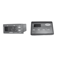
Details unit components for Climatic 200/400 and introduces remote controller option.
Explains the 3-digit display, compressor, mode, defrost, and electrical heater LEDs, and button functions.
Details the 3-digit display, LEDs, and button functions for the Climatic 400 keypad.
Describes the remote controller's display, LEDs, and button operations for the RC Climatic 200.
Explains the functions of the RC Climatic 400 remote controller's display, LEDs, and buttons.
Details the initial power supply and unit ON/OFF procedures for commissioning.
Explains how to select between COOL, HEAT, and STAND-BY operating modes.
Describes the process for adjusting the cooling and heating set points for water temperature.
Explains how to enter and move through the unit's menu structure using buttons.
Provides a breakdown of menu levels like Set Point, Alarms, Parameters, Password, and Hours.
Explains compressor control based on water temperature and set point in cooling mode.
Details compressor control based on water temperature and set point in heating mode.
Lists codes (E01-E06) and their corresponding probe values for temperature/pressure inputs.
Defines each probe (St1 to St6) and the temperatures/pressures they measure.
Covers remote ON/OFF control and remote changeover for summer/winter modes.
Details the dynamic set point feature using an outdoor temperature probe for energy saving.
Illustrates dynamic set point adjustment based on outdoor temperature for cooling and heating.
Explains connecting the unit to a BMS system using Modbus protocol and gateways.
Details how to navigate to the parameter menu using buttons and displays.
Lists categories: General, Compressor, Fan, Alarms, Water Pump, Anti-freeze, Defrost.
Provides adjustable parameters, ranges, defaults, and units for Climatic 200.
Lists adjustable parameters, ranges, defaults, and units for Climatic 400.
Explains how to display compressor and water pump operating hours via the menu.
Details the procedure for resetting the operating hours counters for compressors and pumps.
Explains alarm display, reset types (AUTO/MAN), and initial alarm codes (E00-E04).
Describes effect and action for High Pressure, Low Pressure, and Thermal Protection alarms.
Covers Anti-freeze, Outlet Temp, Piping Temp, High/Low Pressure, and Compressor 2 thermal alarms.
Details Circuit 2 High/Low Pressure, and Compressor 2 thermal protection alarms.
Covers fan thermal, piping probe, and circuit 2 pressure/temperature alarms.
Details alarms for inlet temp probe, water flow, St4 probe, config error, and high inlet temp.
Explains defrost activation, initial/end conditions, delays, and maximum duration.
Details the step-by-step sequence of the defrost cycle, including valve and compressor actions.
Explains fan speed control based on ambient temperature for specific models.
Describes 2-speed fan operation managed by condensing pressure or ambient thermostat.
Covers anti-freeze activation based on outlet water temp and low water temp alarm conditions.
Details compressor start delay, crankcase heaters, and water pump start delay safety features.
| Brand | Lennox |
|---|---|
| Model | CLIMATIC 200 |
| Category | Network Router |
| Language | English |