2
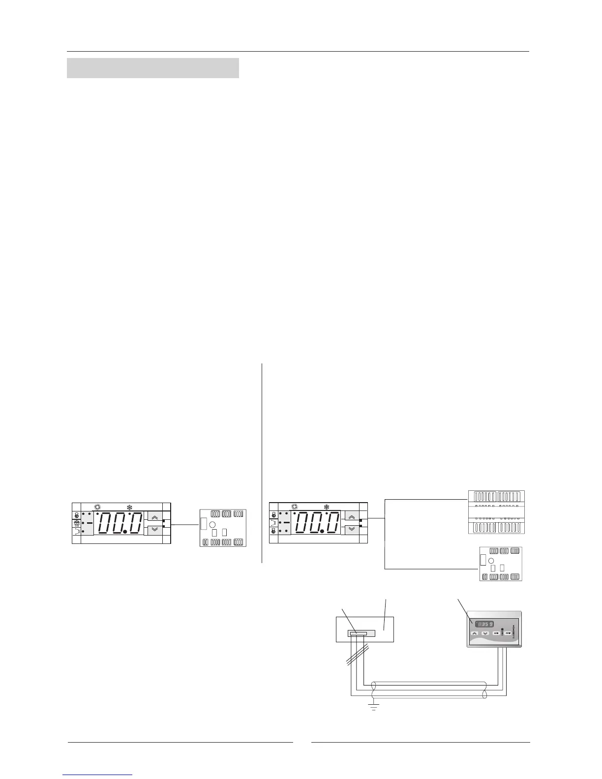
Three-lead shielded cable
with a cross-section of
1 mm
2
*
Terminal block
Remote controller (option)
2
1
x 1000
Electrical box at the unit
The three cables for connection from the keypad to
the power board must be kept separate from other
cables, using an individual cable channel; and use
shielded cables, with a cross-section of 1 mm
2
.
This equipment is an electronic device that controls packaged water cooling systems via air and reversible air/water
heat pumps: (EAC/EAR 0251SM to 1804SM).
The thermostat allows the following operations:
- Unit ON/OFF.
- Select system operating mode.
- Set point adjustment.
- Alarm signal relay.
- Display temperature.
- Status of the unit alarms.
- Possibility of remote ON/OFF.
- A remote controller as an option.
MODEL Climatic
®
400
(2 circuit unit model
EAC 1003 to 1804 and EAR 1003 to 1804)
-
Keypad:
Located in the unit.
- Control Module:
Located at the electrical box.
This device controls the operation of the unit
, allowing the regulation
of the system.
*Connection to be made by customer
MAXIMUM LENGTH 50m
The control incorporated in the unit contains the following devices:
MODEL Climatic
®
200 (1 circuit unit model
EAC 0251 to 0812 and EAR 0251 to 0812)
-
Keypad:
Located in the unit.
The keypad provides control of the system.
- Fan Control Plate:
Located at the electrical box.
Allows the fan speed to be varied with respect to
the condensing temperature (only for Standard and
FP1 units).
A remote controller is offered as an option.
To install this optional remote controller proceed as follow:
- Connect exactly as indicated in electrical diagram.
- The wire should not exceed 50 m.
OPTION
Keypad located in the unit
Fan control plate
Climatic
®
200
set
mode
on off
1
2
Keypad located in the unit
Control Module
Fan control plate
Climatic
®
400
set
mode
on off
1
2
3
4
GENERAL DESCRIPTION
REGULATION:
The control makes the system regulation as follow:
- Receives the signals of analogue inputs through the inlet and outlet probe temperature values and the refrigerant
piping probe temperature/pression(the probe is placed in the plater/exchanger) two for model Climatic
®
400.
- Receives digital inputs through the status of low and high pressure switches, flow switch (water flow) status and
from electrical protection of fan and compressor.
According to the values and status of analogue and digital inputs manages: the output signals; compressor, fan
and status of water pump operating, obtaining the regulation of the inlet water temperature to the unit, regulating
the speed of the air fan volume, activating the defrost cycle (heat pump units only); output signals water exchange
heater, water tank heater, and hot gas valve (all these elements are an option) used to protect the unit, and also
activates the alarm codes about, setting pressure switches, flow switch, water flow, and the electrical protection
of fan and compressor (see alarm section).
- A group of parameters let the control be programmed for each application.
 Loading...