Page 7
XC15 SERIES
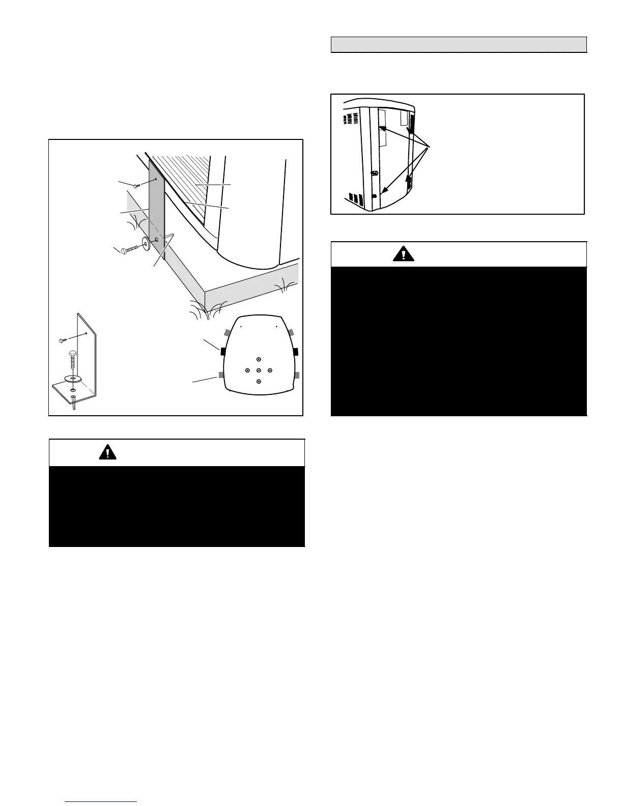
STABILIZING UNIT ON UNEVEN SURFACES
To help stabilize an outdoor unit, some installations may
require strapping the unit to the pad using brackets and
anchors commonly available in the marketplace.
With unit positioned at installation site, remove two side
louvered panels to expose the unit base pan. Install the
brackets as illustrated in figure 12 using conventional
practices; replace the panels after installation is complete.
ONE BRACKET PER SIDE (MIN.); FOR EXTRA STABILITY,
2 BRACKETS PER SIDE, 2" FROM EACH CORNER.
CONCRETE SLAB − USE PLASTIC
PLASTIC ANCHOR (HOLE DRILL
1/4")PLASTIC SLAB − NO PLASTIC
ANCHOR (HOLE DRILL 1/8")
COIL
BASE PAN
CORNER POST
STABILIZING
BRACKET (18 GAUGE
METAL − 2" WIDTH;
HEIGHT AS REQ’D)
Slab Side Mounting
#10 1/2" LONG SELF−
DRILLING SHEET
METAL SCREWS
#10 1−1/4" LONG
HEX HD SCREW
AND FLATWASHER
MINIMUM 1
PER SIDE
Deck Top
Mounting
STABILIZING BRACKET
(18 GAUGE METAL − 2"
WIDTH; HEIGHT AS
REQ’D); BEND TO FORM
RIGHT ANGLE
FOR EXTRA
STABILITY
Figure 12. Installing Stabilizer Brackets
IMPORTANT
Unit Stabilizer Bracket Use (field−provided):
Always use stabilizers when unit is raised above the
factory height. (Elevated units could become
unstable in gusty wind conditions).
Stabilizers may be used on factory height units
when mounted on unstable an uneven surface.
ROOF MOUNTING
Install unit at a minimum of four inches above the surface
of the roof. Care must be taken to ensure weight of unit is
properly distributed over roof joists and rafters. Either
redwood or steel supports are recommended.
Removing and Installing Panels
ACCESS PANEL
Remove and reinstall access panel as shown in figure 13.
REMOVE 4 SCREWS TO REMOVE PANEL
FOR ACCESSING COMPRESSOR AND
CONTROLS.
INSTALL BY POSITIONING PANEL WITH
HOLES ALIGNED; INSTALL SCREWS AND
TIGHTEN.
Figure 13. Access Panel
CAUTION
To prevent personal injury, or damage to panels,
unit or structure, be sure to observe the following:
While installing or servicing this unit, carefully stow
all removed panels out of the way, so that the panels
will not cause injury to personnel, nor cause
damage to objects or structures nearby, nor will the
panels be subjected to damage (e.g., being bent or
scratched).
While handling or stowing the panels, consider any
weather conditions, especially windy conditions,
that may cause panels to be blown around and
battered.
INSTALLING ISOLATION GROMMETS
Locate the isolation grommets (provided). Slide grommets
onto suction and liquid lines. Insert grommets into mullion
to isolate refrigerant lines from sheet metal edges.
REMOVING PANELS
Remove the louvered panels as follows:
1. Remove two screws, allowing the panel to swing open
slightly as illustrated in figure 14.
NOTE − Hold the panel firmly throughout this procedure
2. Rotate bottom corner of panel away from hinge corner
post until lower three tabs clear the slots as illustrated
in figure 14, detail B.
3. Move panel down until lip of upper tab clears the top
slot in corner post as illustrated in figure 14, detail A.

 Loading...