EasyManua.ls Logo

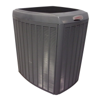
Lennox Dave Lennox Signature SL28XCV User Manual

Lennox Dave Lennox Signature SL28XCV
23 pages
To Next Page IconTo Next Page
Page #1 background imageLoading...
Page #1 background image
©2020 Lennox Industries Inc.
Dallas, Texas, USA
Page 1
General
This SL28XCV outdoor air conditioner with all-aluminum
coil is designed for use with HFC-410A refrigerant only.
These instructions are intended as a general guide and do
not supersede local codes in any way. Consult authorities
having jurisdiction before installation.
INSTALLATION
INSTRUCTIONS
AIR CONDITIONER
508022-01
3/2020
Dave Lennox Signature
®
Collection SL28XCV System
WARNING
Improper installation, adjustment, alteration, service
or maintenance can cause property damage, personal
injury or loss of life. Installation and service must be
performed by a licensed professional HVAC installer or
equivalent, or service agency.
IMPORTANT: Special procedures are required for clean-
ing the all-aluminum coil in this unit. See page 20 in this
instruction for information.
CONTROL
PANEL ACCESS
LOCATION
6 (152)
36 (914)
12 (305)
30 (762)
24
(610)
LINE SET
CONNECTIONS
ACCESS
PANEL
REAR VIEW OF UNIT
48 (1219)
MINIMUM CLEARANCE BETWEEN TWO UNITS
CLEARANCE ON ALL SIDES — INCHES (MILLIMETERS)
MINIMUM CLEARANCE
ABOVE UNIT
NOTES:
Clearance to access panel must be 30
inches (762mm).
Clearance to one of the other three
sides must be 36 inches (914mm).
Clearance to one of the remaining two
sides may be 12 inches (305mm) and
the final side may be 6 inches
(152mm).
Note: Dimensions are not to scale.
THIS UNIT IS A INTEGRAL COMPONENT OF A SYSTEM THAT
WILL REQUIRE A COMMUNICATING THERMOSTAT AND
COMMUNICATING AIR HANDLER OR FURNACE.
SL28XCV
Communicating air handler
or furnace
Communicating
thermostat
SETTING THE UNIT – Clearances
THIS MANUAL MUST BE LEFT WITH THE
HOMEOWNER FOR FUTURE REFERENCE
PACKING LIST
OUTDOOR UNIT
WARRANTY
CARD
GROMMETS (2)
BUSHING (1)
RAST 6-PIN
CONNECTOR (1)
This unit must be installed with an approved indoor air
handler or coil. For AHRI Certied system match-ups and
expanded ratings, visit www.LennoxPros.com.
Question and Answer IconNeed help?

Do you have a question about the Lennox Dave Lennox Signature SL28XCV and is the answer not in the manual?

Lennox Dave Lennox Signature SL28XCV Specifications

General IconGeneral
SEER RatingUp to 28
Cooling Capacity2 to 5 tons
Cooling StagesVariable
RefrigerantR-410A
Energy Star CertifiedYes
Compressor TypeVariable-Capacity
Warranty10-Year Limited Warranty
ClimateDesigned for all climates

Summary

General Information

Unit Overview and System Requirements

Details the SL28XCV unit, its refrigerant, and system needs.

Packing List

Included Components

Lists the components provided in the unit's packing.

Unit Clearances

Clearances on All Sides

Specifies required clearances around the outdoor unit on all sides.

Minimum Clearance Above Unit

Details the minimum required vertical clearance for the outdoor unit.

Minimum Clearance Between Units

Outlines minimum spacing required between multiple outdoor units.

Outdoor Unit Placement

General Placement Guidelines

Instructions for unit placement away from windows and on level surfaces.

Slab Mounting Methods

Details for mounting on concrete slabs, including side and deck top.

Stabilizing on Uneven Surfaces

Methods for stabilizing the unit on uneven ground or surfaces.

Unit Dimensions

Physical Dimensions and Specifications

Provides detailed measurements and specifications for the unit's physical size.

Unit Placement Considerations

Roof Installation and Materials

Notes on potential roof damage from oil and proper placement.

System Matching and Coil Flushing

Requirements for matching indoor coils and flushing older systems.

Installation Warnings and Precautions

Safety warnings for panel handling, exhaust gases, and sharp edges.

Refrigerant Piping - General Notes

Oil Type and Flushing Procedures

Information on PVE oil and flushing systems with POE oil.

Line Set Sizing and Guidelines

Guidance on selecting line set sizes and references for design guidelines.

Refrigerant Handling Regulations

Mentions the Clean Air Act ban on venting refrigerant and pressure handling.

Refrigerant Handling and Safety

Refrigerant Hazards and Precautions

Warnings about inhaling refrigerant and fire/explosion hazards.

Oil and Moisture Sensitivity

Importance of keeping the system closed due to PVE oil's moisture absorption.

Compressor Protection

Notes on internal vacuum protectors and avoiding compressor replacement.

Adding Refrigerant for Long Line Sets

Weigh-In Method and Adjustments

Procedure for adjusting refrigerant charge based on line set length and diameter.

Refrigerant Line Set Sizing

Standard Line Sets Up to 50 Feet

Table detailing recommended line set sizes and catalog numbers.

Line Sets Between 51-150 Feet

Guidelines for selecting line set dimensions for longer runs.

Liquid Line Diameter Selection

Table for selecting liquid line size based on total linear length and elevation.

Brazing Safety Precautions

Warnings regarding brazing alloys, flux, and handling.

Refrigerant Piping - Metering Device Removal and Flushing

Fixed Orifice Metering Device Removal

Procedure for removing existing fixed orifice devices.

Expansion Valve Metering Device Removal

Procedure for removing existing expansion valve devices.

Flushing Line Set Procedure

Step-by-step guide for flushing the line set with refrigerant.

Refrigerant Piping - Brazing Procedures

Preparing Line Set for Brazing

Steps for removing panels and preparing line set ends.

Cap and Core Removal

Instructions for removing service port caps and cores.

Attaching Manifold Gauge Set

How to connect the manifold gauge set for brazing.

Refrigerant Piping - Brazing and Cooling

Wrapping Service Valves

Protecting service valves and tubes with water-saturated cloths.

Nitrogen Flow During Brazing

Procedure for flowing nitrogen at low pressure during brazing.

Brazing Line Set and Cooling

Steps for brazing the line set and cooling the joints.

Refrigerant Piping - Expansion Valve Installation

Indoor Expansion Valve Installation

Steps for installing the expansion valve unit.

Sensing Bulb Installation

Guidelines for installing the vapor line sensing bulb correctly.

Equalizer Line Installation

Procedures for installing the equalizer line connection.

Leak Test and Evacuation

Connecting Gauge Set for Leak Test

How to connect the manifold gauge set for leak testing.

Leak Testing Procedure

Steps to test the line set and indoor unit for leaks.

System Evacuation

Connecting Gauge Set for Evacuation

Connecting the gauge set, micron gauge, and vacuum pump.

Evacuating the System

Procedure for evacuating the line set and indoor unit to the required vacuum.

Electrical - Circuit Sizing and Wiring

Circuit Sizing and Disconnect Switch

Guidance on sizing circuits, breakers, and installing disconnect switches.

Thermostat Installation

Recommendations for thermostat placement and installation.

Electrical Safety Warnings

Warnings about high voltage, fire hazards, and electrostatic discharge.

Outdoor Control (A175) Details

Jumpers and Terminals Overview

Identifies key terminals, jumpers, and the 7-segment display on the control board.

Pump Down Mode Activation

How to activate and deactivate the unit's pump down mode.

Typical Field Wiring Diagrams

Outdoor Unit Wiring Connections

Diagram showing typical wiring connections for the outdoor unit.

Indoor Unit Wiring Connections

Diagram showing typical wiring connections for the indoor unit.

Electrical Safety and Wire Notes

Safety warnings and notes regarding wire replacement and grounding.

Typical Factory Wiring Diagram

Control Panel and Component Wiring

Detailed factory wiring diagram of the control panel and components.

General Wiring Notes and Best Practices

Best practices for routing, bundling, and terminating wires.

Routing Control and High Voltage Wires

Routing Low Voltage Control Wires

Guidelines for routing thermostat and communication wiring.

Routing High Voltage and Ground Wires

Instructions for routing power wiring and ground connections.

Communicating Thermostat Wiring

SL28XCV with iComfort S30 Wiring

Field wiring diagram for connecting the SL28XCV with the iComfort S30 thermostat.

Unit Start-Up Procedures

Pre-Start Up Checks

Essential checks before energizing the unit, including crankcase heater.

Torque Requirements

Table of recommended torque values for various fasteners.

Operating Service Valves

How to operate ball-type and angle-type service valves.

Charging and System Operation

Operating Angle-Type Service Valves

Detailed steps for operating angle-type service valves.

Refrigerant Charging Procedure

How to check and adjust refrigerant charge for different line lengths.

Alarm and Display Information

Information on unit alarms and the outdoor control seven-segment display.

System Maintenance and Troubleshooting

High Pressure Switch Function

Explanation of the high pressure switch operation.

Homeowner Maintenance Tasks

Recommended maintenance tasks for the homeowner, like filter checks.

Professional Maintenance and Coil Cleaning

Guidance for professional service and cleaning aluminum coils.

Service and Inspection Procedures

Outdoor Unit Inspection Points

Key inspection points for the outdoor unit during service.

Indoor Unit Inspection Points

Key inspection points for the indoor unit during service.

General System Operating Test

Steps for performing a general system test with the unit operating.

Start-Up and Performance Checklist

Start Up Checks and Data Entry

Fields for recording system data during start-up.

Cooling Mode Calculations

How to calculate subcooling, approach, and coil temperature drop.
Related product manuals