Page 15
11. Combustion Air Inducer
Pressure Switch (S18)
EL180UHE(X) series units are equipped with a combustion
air pressure switch located on the combustion air inducer
orifice bracket. The switch is connected to the combustion
air inducer housing by means of a flexible silicone hose. It
monitors negative air pressure in the combustion air induc
er housing.
The switch is a single‐pole single‐throw proving switch
electrically connected to the furnace control. The purpose
of the switch is to prevent burner operation if the combus
tion air inducer is not operating or if the flue becomes ob
structed.
On start‐up, the switch senses that the combustion air in
ducer is operating. It closes a circuit to the integrated con
trol when pressure inside the combustion air inducer de
creases to a certain set point. Set points vary depending on
unit size. See table 7. The pressure sensed by the switch is
negative relative to atmospheric pressure. If the flue be
comes obstructed during operation, the switch senses a
loss of negative pressure (pressure becomes more equal
with atmospheric pressure) and opens the circuit to the in
tegrated control and gas valve. A bleed port on the switch
allows relatively dry air in the vestibule to purge switch tub
ing, to prevent condensate build up.
TABLE 7
EL180UHE(X)
inches w.c.
Make
Break + 0.05
045E36A -0.75 -0.65
070E36B -0.83 -0.68
090E48B, 090E60C -0.80 -0.65
110E60C -0.83 -0.68
135E60D -0.80 -0.65
The switch is factory set and is not field adjustable. It is a
safety shut‐down control in the furnace and must not be by-
passed for any reason. If switch is closed or by-passed, the
integrated control will not initiate ignition at start up.
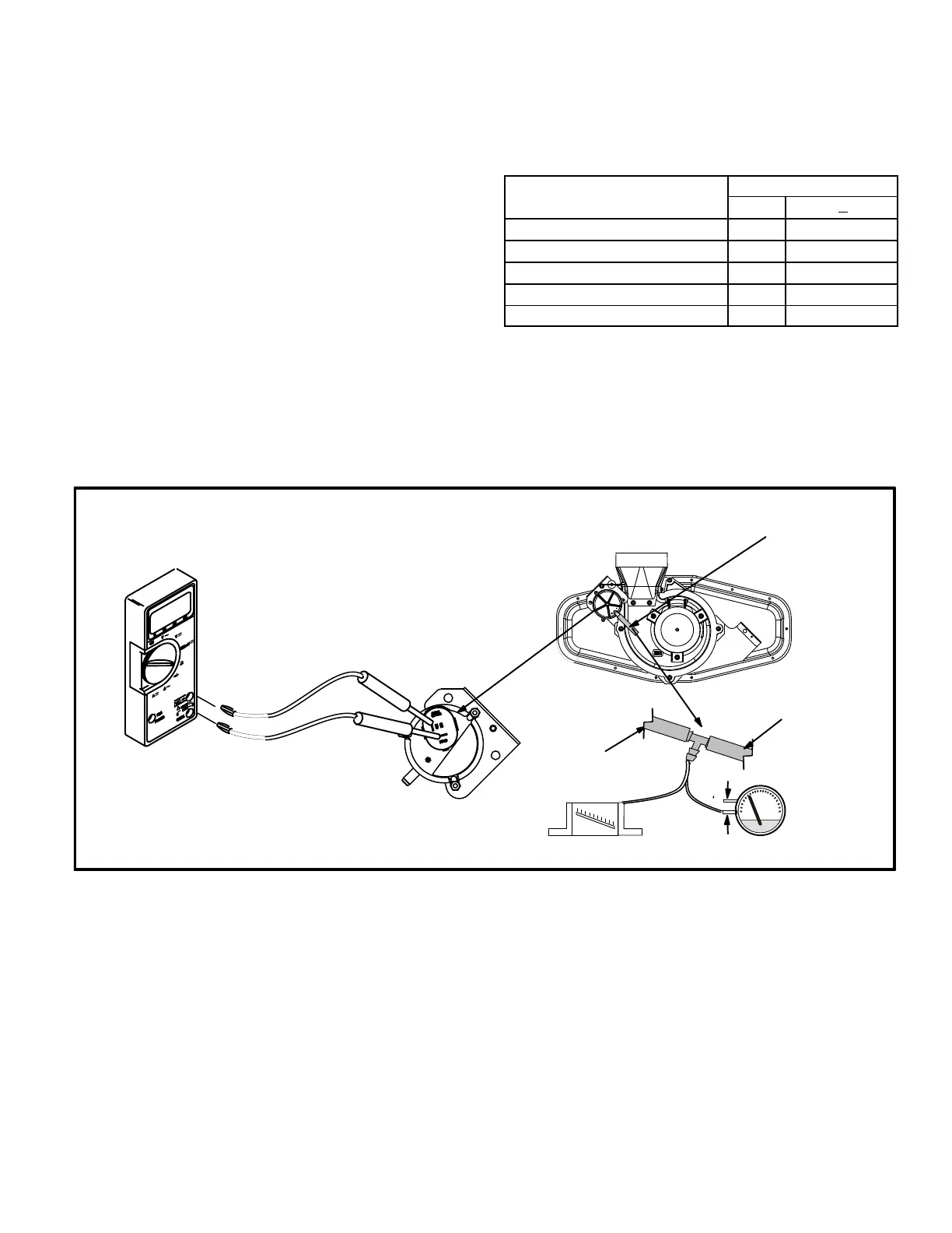
Troubleshooting
See figure 10 for measuring operating pressure and check
ing resistance in the pressure switch.
FIGURE 10
MULTI−METER
SET TO MEASURE OHMS
+
-
or
Field Provided
Tubing To CAI
Port
To Pressure Switch
Remove tubing from CAI and
insert “Tee” and additional tubing.
High
Low
 Loading...