Do you have a question about the Lennox EL180UHE SERIES and is the answer not in the manual?
Essential safety precautions for installation and operation.
Detailed performance and physical specs for gas and blower components.
Required spacing for safe installation in upflow and horizontal positions.
Lists optional parts for cabinet, filters, and gas conversion.
Accessories for gas heat operation, including pressure switches.
Information on derating unit performance at higher altitudes.
Performance data for the EL180UH045E36A model.
Performance data for the EL180UH070E36B model.
Performance data for the EL180UH090E60C model.
Performance data for the EL180UH110E60C model.
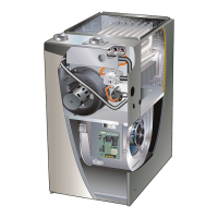
Diagram labels major components like heat exchanger, gas valve, and blower.
Provides power to the low voltage section of the unit.
Safety switch that shuts down unit when blower door removed.
Provides overcurrent protection to the transformer.
Manages all major furnace operations and ignition sequence.
Mapping of pin numbers to specific functions on the control board.
Visual layout of the integrated control board with terminal labels.
List of RED LED flash codes and their corresponding furnace status.
Diagram illustrating the sequence of events during electronic ignition.
Instructions on adjusting the fan off delay for optimal comfort.
Information on the factory-set cooling fan off delay.
High temperature limit switches that prevent operation during rollout.
Limit control that opens on excess heat in the heat exchanger.
Detects flame presence for safe burner operation.
Step-by-step guide to measure flame signal in microamps.
Table showing normal, low, and drop-out ranges for flame signal.
Information on the gas valve and corresponding orifice sizes for different models.
Explains the role of the inducer in operation and its pressure switch.
Details on the nitride ignitor, including resistance and voltage checks.
Tests for checking ignitor resistance using an ohmmeter.
Tests for checking the voltage supplied to the ignitor.
How the switch proves inducer operation and detects flue obstruction.
Table listing make and break pressure set points for different models.
Diagrams and notes on achieving vertical or horizontal vent discharge.
Steps for troubleshooting the ECM blower motor.
Importance of correct blower wheel placement in the housing.
Tests for 120VAC and 24VDC supply to the blower motor.
Steps for mounting and connecting the replacement motor control module.
Tests to check resistance and motor continuity before replacement.
Step-by-step guide for safely starting the furnace for heating.
Procedures for testing gas piping and general safety precautions.
Methods for adjusting and measuring gas pressure and flow rates.
Guidelines for checking CO levels and combustion efficiency.
Settings for different altitudes and gas types.
Kits and settings for pressure switches at various altitudes.
Checking furnace grounding for correct flame sense signal.
Measuring AC voltage at the integrated control terminals.
General procedure for blower operation and thermostat control.
Factors affecting temperature rise and how to set blower speed.
Procedure for measuring static pressure in supply and return air.
Inspecting wiring, voltage, and general system readiness.
Guidance on filter inspection, cleaning, and replacement.
Steps for cleaning the heat exchanger, burners, and inducer.
Instructions for reassembling the burner box and manifold.
Procedures and precautions for checking gas piping for leaks.
Instructions for checking and cleaning the blower wheel.
Verifying wiring connections and checking motor amp-draw.
Diagram illustrating electrical connections for furnace components.
Detailed steps of the furnace operation during heating mode.
Step-by-step guide to identify and resolve heating operational issues.
Further diagnosis of abnormal heating modes and error codes.
Step-by-step guide to identify and resolve cooling operational issues.
Diagnosing issues related to the continuous fan mode.