Page 13
8. Gas Valve (Figure 6)
The EL180UHE(X) uses an internally redundant gas valve
to assure safety shut-off. If the gas valve must be replaced,
the same type valve must be used.
24VAC terminals and valve switch are located on the
valve. All terminals on the gas valve are connected to wires
from the integrated control. 24V applied to the terminals
energizes the valve.
Inlet and outlet pressure taps are located on the valve. A
regulator adjustment screw is located on the valve.
LPG changeover kits are available from Lennox. Kits in
clude burner orifices and a gas valve regulator spring.
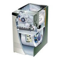
9. Combustion Air Inducer (B6)
All EL180UHE(X) units use a combustion air inducer to
move air through the burners and heat exchanger during
heating operation. The blower uses a 120VAC motor. The
motor operates during all heating operation and is con
trolled by integrated control A92. The inducer also oper
ates for 15 seconds before burner ignition (pre‐purge) and
for 5 seconds after the gas valve closes (post‐purge).
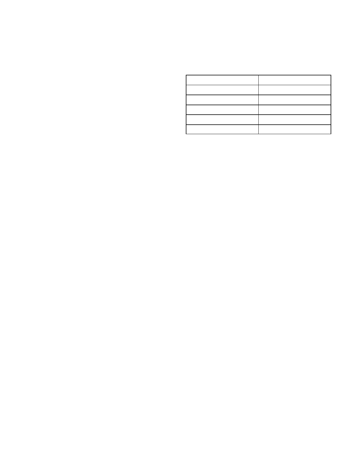
A pressure switch mounted on the combustion air inducer
orifice plate is used to prove inducer operation. The com
bustion air inducer orifice will be different for each model.
See table 6 for orifice sizes. The switch monitors air pres
sure in the inducer housing. During normal operation, the
pressure in the housing is negative. If pressure becomes
less negative (signifying any obstruction in the flue) the
pressure switch opens. When the pressure switch opens,
the integrated control (A92) immediately de-energizes the
gas valve to prevent burner operation.
TABLE 6
EL180UHE(X) Unit
C.A.I. Orifice Size
045E36A 1.063”
070E36B 1.316”
090E48B, 090E60C 1.531”
110E60C 1.690”
135E60D 1.940”
10. Ignitor (Figure 6)
The nitride ignitor used on EL180UHE units is made from a
proprietary ceramic material. To check ignitor, measure its
resistance and voltage. A value of 39 to 70 ohms indicates
a good ignitor. Voltage to the ignitor should be 120VAC.
See figure 9 for resistance, and voltage check.
NOTE - The EL180UHE(X) furnace contains electronic
components that are polarity sensitive. Make sure that the
furnace is wired correctly and is properly grounded.
 Loading...