Page 2
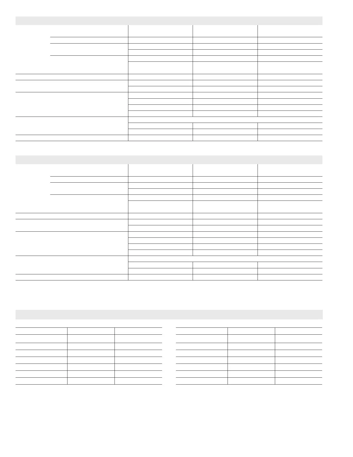
SPECIFICATIONS
Gas
Heating
Performance
Model No. EL180UH045E36A EL180UH070E36B EL180UH090E48B
ELModel No. - Low Nox EL180UH045XE36A EL180UH070XE36B 180UH090XE48B
1
AFUE 80% 80% 80%
Input - Btuh 44,000 66,000 88,000
Output - Btuh 35,200 52,800 70,400
Temperature rise range - °F 15 - 45 40 - 70 35 - 65
Gas Manifold Pressure (in. w.g.)
Nat. Gas / LPG/Propane
3.5 / 10.0 3.5 / 10.0 3.5 / 10.0
High Static - in. w.g. 0.50 0.50 0.50
Connections
in.
Flue connection - in. round 4 4 4
Gas pipe size IPS 1/2 1/2 1/2
Indoor
Blower
Wheel nom. dia. x width - in. 10 x 8 10 x 10 10 x 10
Motor output - hp 1/2 1/2 3/4
Tons of add-on cooling 1.5 - 3 1.5 - 3 2.5 - 4
Air Volume Range - cfm 350 - 1380 345 - 1330 750 - 1785
Electrical
Data
Voltage 120 volts - 60 hertz - 1 phase
Blower motor full load amps 6.8 6.8 8.4
Maximum overcurrent protection 12 12 12
Shipping Data lbs. - 1 package 111 127 142
SPECIFICATIONS
Gas
Heating
Performance
Model No. EL180UH090E60C EL180UH110E60C EL180UH135E60D
Model No. - Low Nox - - - EL180UH110XE60C - - -
1
AFUE 80% 80% 80%
Input - Btuh 88,000 110,000 132,000
Output - Btuh 70,400 88,000 105,600
Temperature rise range - °F 30 - 60 35 - 65 30 - 60
Gas Manifold Pressure (in. w.g.)
Nat. Gas / LPG/Propane
3.5 / 10.0 3.5 / 10.0 3.5 / 10.0
High Static - in. w.g. 0.50 0.50 0.50
Connections
in.
Flue connection - in. round 4 4 4
Gas pipe size IPS 1/2 1/2 1/2
Indoor
Blower
Wheel nom. dia. x width - in. 11-1/2 x 10 11-1/2 x 10 11 x 11
Motor output - hp 1 1 1
Tons of add-on cooling 3 - 5 3 - 5 3.5 - 5
Air Volume Range - cfm 990 - 2290 920 - 2315 1140 - 2495
Electrical
Data
Voltage 120 volts - 60 hertz - 1 phase
Blower motor full load amps 10.9 10.9 10.9
Maximum overcurrent protection 12 12 12
Shipping Data lbs. - 1 package 152 160 178
NOTE - Filters and provisions for mounting are not furnished and must be eld provided.
1
Annual Fuel Utilization Efciency based on DOE test procedures and according to FTC labeling regulations. Isolated combustion system rating for non-weatherized furnaces.
UPFLOW POSITION
Vent Type Type B1 Type C
Sides 0 (0)
1
0 (0)
Rear 0 (0) 0 (0)
Top 1 (25) 1 (25)
Front 2-1/4 (57) 2-1/4 (57)
Front (service/alcove) 24 (610) 24 (610)
Floor Combustible Combustible
Flue 1 (25) 6 (152)
NOTE − Air for combustion must conform to the methods outlined in the National
Fuel Gas Code (NFPA 54/ANSI-Z223.1).
NOTE − In the U.S. ue sizing must conform to the methods outlined in the
current National Fuel Gas Code (NFPA 54/ANSI-Z223.1) or applicable
provisions of local building codes.
1
Left side requires 4 in. if single wall vent is used on 14-1/2 in. cabinets, 2 in. on
17-1/2 in. cabinets.
INSTALLATION CLEARANCES - INCHES (MM)
HORIZONTAL POSITION
Vent Type Type B1 Type C
End
1
2
1
2
Rear 0 (0) 0 (0)
Top
1
0 (0)
1
0 (0)
Front 2-1/4 (57) 2-1/4 (57)
Front (service) 24 (610) 24 (610)
Floor Combustible Combustible
Flue 1 (25) 6 (152)
NOTE − Air for combustion must conform to the methods outlined in the National
Fuel Gas Code (NFPA 54/ANSI-Z223.1).
NOTE − In the U.S. ue sizing must conform to the methods outlined in the
current National Fuel Gas Code (NFPA 54/ANSI-Z223.1) or applicable
provisions of local building codes.
1
Line contact installation permissible between jacket top or sides and building
joists.
 Loading...