Page 17
12. Blower Motor
IMPORTANT
Each blower is statically and dynamically bal
anced as an assembly before installation in the
unit.
EL180UHE units are equipped with a constant torque ECM
motor. It has a DC motor coupled to an electronic control
module both contained in the same motor housing. The
motor is programmed to provide constant torque at each of
the five selectable speed taps. Each tap requires 24 volts to
energize.
Input Voltage Requirements
The circuit is designed to be operated with AC voltage. To
enable a tap requires 12 to 33VAC. Expected current draw
will be less than 20mA.
Troubleshooting the Motor
Troubleshooting the motor is an easy process. Follow
steps below.
1- Shut off power to unit.
2- Remove input plugs P48 and P49 from motor. See fig
ure 14 for troubleshooting procedure.
If correct voltage is present in tests 1 and 2 and motor is not
operating properly, replace motor. The motor is not field re
pairable.
If replacing the indoor blower motor or blower wheel is nec
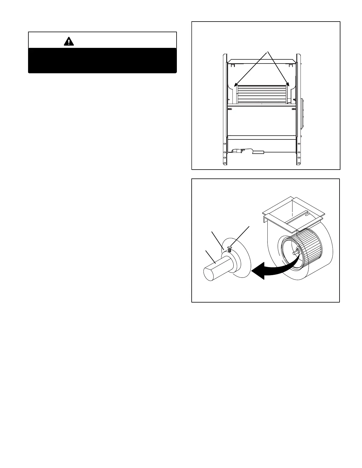
essary, placement is critical. The blower wheel must be
centered in the blower housing as shown in figure 12.
When replacing the indoor blower motor the set screw
must be aligned and tightened with the motor shaft as
shown in figure 13.
FIGURE 12
Center Blower Wheel
in Blower Housing
BLOWER WHEEL REPLACEMENT
FIGURE 13
Set Screw
Housing Hub
ALIGN AND TIGHTEN SET SCREW WITH
FLAT SIDE OF MOTOR SHAFT
Motor
Shaft
 Loading...