Do you have a question about the Lennox EL195UHE and is the answer not in the manual?
| Model | EL195UHE |
|---|---|
| Type | Gas Furnace |
| Efficiency Rating | 95% AFUE |
| Stages | Two-stage |
| Blower Type | Variable-Speed |
| Fuel Type | Natural Gas or Propane |
| Warranty | Limited Lifetime Heat Exchanger, 10-year Parts |
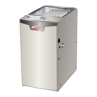
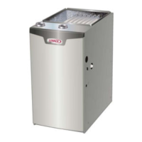
General introduction to the EL195UHE series gas furnaces, their features, and applications.
Essential safety precautions regarding electrical hazards, installation, and handling sharp edges.
Details on heating performance, gas/drain connections, and blower specifications.
Electrical requirements and shipping weight information for the units.
Optional accessories for cabinet mounting, condensate drainage, and air filtration.
Termination kits for venting and accessories for gas heating systems.
Air volume and wattage performance data for the 045 model.
Air volume and wattage performance data for the 070 model.
Air volume and wattage performance data for the 090 model.
Air volume and wattage performance data for the 110 model.
Air volume and wattage performance data for the 135 model.
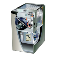
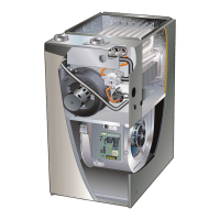
Diagram illustrating the location of key furnace components.
Guidelines for handling static-sensitive components and identifying parts within the control box.
Details on transformer, interlock switch, circuit breaker, and ignition control.
Reference for identifying various quick connect terminals on the control board.
List of LED flash codes indicating furnace status and error conditions.
Explanation of the ignition process, safety interlocks, and control board functions.
Information on how to adjust fan on/off delays for heating and cooling.
Description of the combustion air inducer, flame rollout switches, heat exchanger, and primary limit control.
Detailed explanations of the gas valve, flame sensor, and ignitor operation and testing.
Data on flame signal values and instructions for measuring it.
Step-by-step guide for testing the ignitor's electrical properties.
Explanation of the inducer, header box, and the function/troubleshooting of the pressure switch.
Detailed instructions and diagram for measuring pressure differential using a manometer.
Table and guidance for diagnosing issues related to the pressure switch.
Visual representation of the furnace's heating cycle and fault detection.
Instructions for blower replacement and explanation of secondary limit controls.
Procedures for testing voltage supplies to the blower motor and its speed taps.
Specifications for approved piping materials, primers, and cements.
Guide to selecting appropriate termination kits for various vent pipe sizes and models.
Instructions for cementing pipe joints, including safety precautions for flammable fumes.
Guidelines for pipe suspension, wall thickness, and safe exhaust pipe termination.
Guidance on determining correct vent pipe size and minimum required lengths.
Table detailing maximum vent pipe lengths for standard terminations at different elevations.
Table detailing maximum vent pipe lengths for concentric terminations at different elevations.
Table specifying maximum vent lengths for installations in confined spaces.
Diagrams illustrating vent pipe connections for upflow installations.
Diagrams illustrating vent pipe connections for horizontal installations.
Instructions and diagrams for installing intake piping in various configurations.
Safety warnings for confined spaces and general rules for vent termination placement.
Table specifying maximum uninsulated vent pipe lengths according to ambient temperature.
Diagram and table detailing clearance requirements for non-direct vent terminations.
Diagram and table detailing clearance requirements for direct vent terminations.
Instructions on routing and terminating exhaust pipes in direct vent systems.
Table specifying reducer sizes for exhaust pipe terminations.
Illustration showing specific measurements for vent termination clearances.
Diagrams illustrating the installation of wall termination kits.
Illustrations of different termination kits for side wall, rooftop, and concentric applications.
Diagram showing the installation of US close-couple extended vent kits.
Diagram showing the installation of Canadian close-couple extended vent kits.
Illustration for direct vent installations using an existing chimney.
Guidance on routing and terminating exhaust piping for non-direct vent systems.
Illustration for non-direct vent installations utilizing an existing chimney.
Instructions for installing condensate traps and drain lines, including safety warnings.
Diagrams illustrating separate condensate drain setups for upflow and horizontal units.
Diagrams detailing common drain configurations, including venting requirements.
Illustrations showing various methods for assembling condensate traps and drains using PVC piping.
Step-by-step instructions for starting the furnace, including safety checks and gas valve operation.
A guide to diagnose and resolve common operational issues.
Procedures for gas piping, leak detection, and pressure testing, including supply and manifold pressures.
Guidance on checking combustion efficiency and requirements for high-altitude installations.
Procedures for verifying proper grounding and voltage levels supplied to the control system.
Explanations of blower function, temperature rise calculations, and static pressure measurement.
Instructions for changing blower speed settings via the integrated control.
Maintenance tasks including blower cleaning, filter inspection, pipe checks, and electrical system verification.
Procedures for seasonal maintenance, including unit winterizing, trap cleaning, and heat exchanger cleaning.
Detailed steps for removing, cleaning, and inspecting the furnace burner assembly.
Instructions for reassembling the burner assembly and ensuring proper furnace operation.
Explanation of the furnace's wiring diagram and the function of various connections.
Step-by-step explanation of how the furnace operates during a heating cycle.
Flowchart detailing the heating sequence and common faults indicated by LED flash codes.
Continuation of the heating sequence troubleshooting, covering more fault conditions and response actions.
Flowchart outlining the cooling cycle, potential issues, and corresponding LED error codes.
Flowcharts illustrating the operation of continuous fan mode and accessory functions.