Page 17
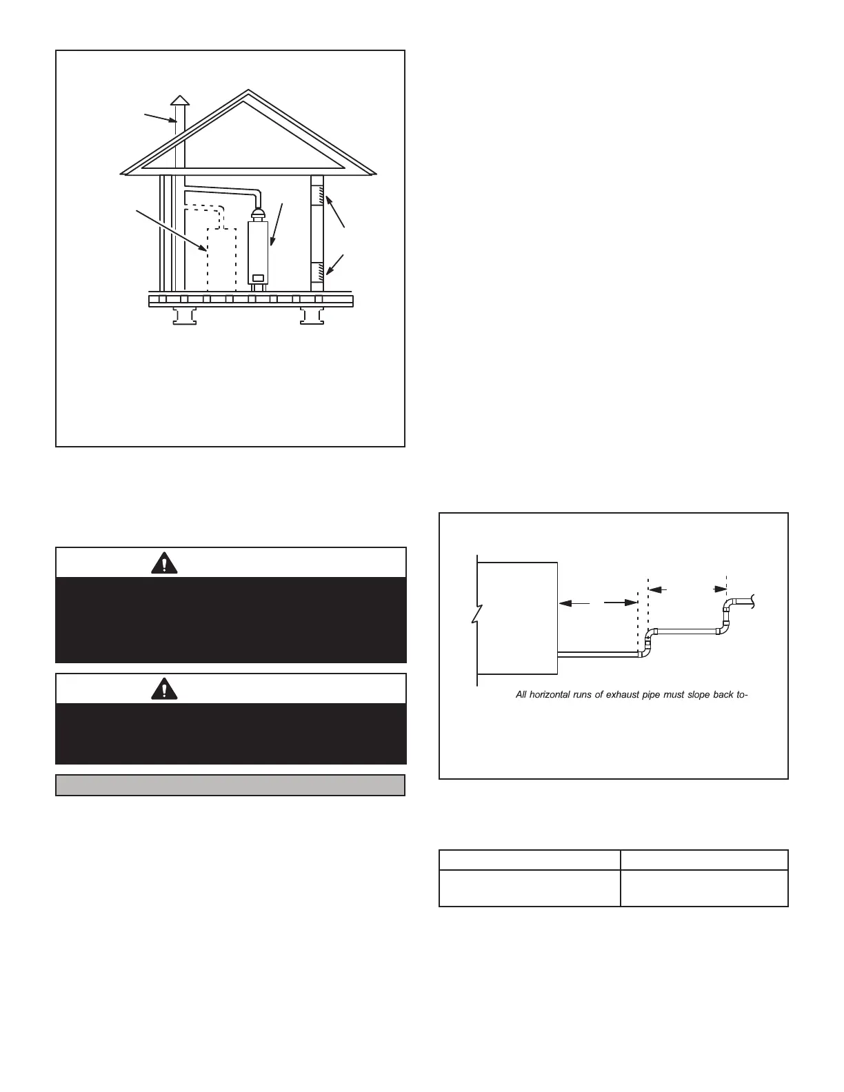
If replacing a furnace which was
commonly vented with another gas appliance, the size
of the existing vent pipe for that gas appliance must be
checked. Without the heat of the original furnace flue
products, the existing vent pipe is probably oversized for
the single water heater or other appliance. The vent
should be checked for proper draw with the remaining
appliance.
REPLACING FURNACE THAT WAS PART OF A
COMMON VENT SYSTEM
CHIMNEY
OR GAS
VENT
(Check sizing
for water
heater only)
FURNACE
(Replaced)
WATER
HEATER
OPENINGS
(To Adjacent
Room)
Figure 22
Exhaust Piping (Figure 25 and Figure 26)
Route piping to outside of structure. Continue with instal-
lation following instructions given in piping termination
section.
CAUTION
Do not discharge exhaust into an existing stack or
stack that also serves another gas appliance. If vertical
discharge through an existing unused stack is required,
insert PVC pipe inside the stack until the end is even
with the top or outlet end of the metal stack.
CAUTION
The exhaust vent pipe operates under positive pressure
and must be completely sealed to prevent leakage of
combustion products into the living space.
Vent Piping Guidelines
NOTE - /HQQR[KDVDSSURYHGWKHXVHRI'XUD9HQWDQG
&HQWURWKHUP PDQXIDFWXUHG YHQW SLSH DQG WHUPLQDWLRQV
DV DQ RSWLRQ WR 39& :KHQ XVLQJ WKH 3RO\3UR E\ 'X-
UD9HQWRU,QQR)OXHE\&HQWURWKHUPYHQWLQJV\VWHPWKH
YHQW SLSH UHTXLUHPHQWV VWDWHG LQ WKH XQLW LQVWDOODWLRQ LQ-
VWUXFWLRQ±PLQLPXPPD[LPXPYHQWOHQJWKVWHUPLQDWLRQ
FOHDUDQFHVHWF±DSSO\DQGPXVWEHIROORZHG)ROORZWKH
LQVWUXFWLRQVSURYLGHGZLWK3R\3URE\'XUD9HQWDQG,QQR-
)OXHE\&HQWURWKHUPYHQWLQJV\VWHPIRUDVVHPEO\RULIUH-
TXLUHPHQWVDUHPRUHUHVWULFWLYH7KH3RO\3URE\'XUDYHQW
DQG ,QQR)OXH E\ &HQWURWKHUP YHQWLQJ V\VWHP PXVW DOVR
IROORZ WKH XQLQVXODWHG DQG XQFRQGLWLRQHG VSDFH FULWHULD
OLVWHGLQ7$%/(
The EL196UHE can be installed as either a Non-Direct
Vent or a Direct Vent gas central furnace.
NOTE - In Non-Direct Vent installations, combustion air
LVWDNHQIURPLQGRRUVDQGÀXHJDVHVDUHGLVFKDUJHGRXW-
GRRUV,Q'LUHFW9HQWLQVWDOODWLRQVFRPEXVWLRQDLULVWDNHQ
IURPRXWGRRUVDQGÀXHJDVHVDUHGLVFKDUJHGRXWGRRUV
,QWDNHDQGH[KDXVWSLSHVL]LQJ 6L]HSLSHDFFRUGLQJ WR
TABLE 4, TABLE 5 and TABLE 6. Count all elbows inside
and outside the home.
Regardless of the diameter of pipe used, the standard roof
and wall terminations described in section Exhaust Piping
Terminations should be used. Exhaust vent termination
SLSHLVVL]HGWRRSWLPL]HWKHYHORFLW\RIWKHH[KDXVWJDVDV
it exits the termination. Refer to TABLE 8.
In some applications which permit the use of several dif-
IHUHQWVL]HVRIYHQWSLSHDFRPELQDWLRQYHQWSLSHPD\EH
used. Contact Lennox’ Application Department for assis-
WDQFHLQVL]LQJYHQWSLSHLQWKHVHDSSOLFDWLRQV
NOTE - 7KHH[KDXVWFROODURQDOOPRGHOVLVVL]HGWRDF-
FRPPRGDWH ´ 6FKHGXOH YHQW SLSH ,Q KRUL]RQWDO DS-
SOLFDWLRQV DQ\ WUDQVLWLRQ WR H[KDXVW SLSH ODUJHU WKDQ ´
PXVWEHPDGHLQYHUWLFDOUXQVRIWKHSLSH7KHUHIRUHD´
HOERZ PXVW EH DGGHG EHIRUH WKH SLSH LV WUDQVLWLRQHG WR
DQ\VL]HODUJHUWKDQ´7KLVHOERZPXVWEHDGGHGWRWKH
HOERZFRXQW XVHG WR GHWHUPLQHDFFHSWDEOHYHQWOHQJWKV
&RQWDFWWKH$SSOLFDWLRQ'HSDUWPHQWIRUPRUHLQIRUPDWLRQ
FRQFHUQLQJVL]LQJRIYHQWV\VWHPVZKLFKLQFOXGHPXOWLSOH
SLSHVL]HV
Horizontal Installation Offset Requirements
NOTE - Exhaust pipe MUST be glued to furnace exhaust fittings.
NOTE -
ward unit. A minimum of 1/4” (6mm) drop for each 12” (305mm)
of horizontal run is mandatory for drainage.
NOTE - Exhaust piping should be checked carefully to make
sure there are no sags or low spots.
12” ma x
of straight pip
e
Exhaust Pipe
12” Min .
Horizontal
Gas Furnace
Figure 23
TABLE 4
MINIMUM VENT PIPE LENGTHS
EL196UHE Model MIN. VENT LENGTH*
030, 045, -070, -090, 110
15 ft. or 5 ft. plus 2 elbows
or 10 ft. plus 1 elbow
*Any approved termination may be added to the minimum
length listed. Two 45 degree elbows are the equivalent to one
90 degree elbow.
 Loading...