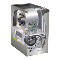
Page 18
Vent Piping Guidelines
NOTE - Lennox has approved the use of DuraVent® and
Centrotherm manufactured vent pipe and terminations as
an option to PVC. When using the PolyPro
®
by DuraVent
or InnoFlue
®
by Centrotherm venting system the vent pipe
requirements stated in the unit installation instruction –
minimum & maximum vent lengths, termination clearanc-
es, etc. – apply and must be followed. Follow the instruc-
tions provided with PoyPro by DuraVent and InnoFlue by
Centrotherm venting system for assembly or if require-
ments are more restrictive. The PolyPro by Duravent and
InnoFlue by Centrotherm venting system must also follow
the uninsulated and unconditioned space criteria listed in
table 8.
The EL296DFV can be installed as either a Non-Direct
Vent or a Direct Vent gas central furnace.
NOTE - In Non-Direct Vent installations, combustion air is
taken from indoors or ventilated attic or crawlspace and
ue gases are discharged outdoors. In Direct Vent instal-
lations, combustion air is taken from outdoors and ue
gases are discharged outdoors.
Intake and exhaust pipe sizing -- Size pipe according to
TABLE 6 (minimum pipe lengths) and TABLE 7 (maxim-
mum pipe lengths). Count all elbows inside and outside
the home.
TABLE 6
MINIMUM VENT PIPE LENGTHS
EL296DFV MODEL MIN. VENT LENGTH*
045, 070, 090, 110
15 ft or 5ft plus 2 elbows or
10 ft plus 1 elbow
*Any approved termination may be added to the minimum
length listed. Two 45 degree elbows are the equivalent to
one 90 degree elbow.
Regardless of the diameter of pipe used, the standard roof
and wall terminations described in section Exhaust Piping
Terminations should be used. Exhaust vent termination
pipe is sized to optimize the velocity of the exhaust gas as
it exits the termination. Refer to TABLE 10.
In some applications which permit the use of several dif-
ferent sizes of vent pipe, a combination vent pipe may be
used. Contact Lennox’ Application Department for assis-
tance in sizing vent pipe in these applications.
IMPORTANT
Do not use screens or perforated metal in exhaust or
intake terminations. Doing so will cause freeze-ups and
may block the terminations.
NOTE - It is acceptable to use any pipe size which ts
within the guidelines allowed in TABLE 7.
NOTE - All horizontal runs of exhaust pipe must slope
backtoward unit. A minimum of 1/4” (6mm) drop for each
12” (305mm) of horizontal run is mandatory for drainage.
NOTE - Lennox oers a glueless vent adapter kit 17H92
as an option for exhaust exiting at the furnace top cap
coupling.
NOTE - Exhaust pipe MUST be glued to furnace exhaust
ttings.
NOTE - Exhaust piping should be checked carefully to
make sure there are no sags or low spots.
NOTE - If right side venting option is used, you must in-
clude the elbow at the furnace in the elbow count. If tran-
sitioning to 3” dia pipe, this elbow equates to 20’ of equiv-
alent vent length for all models.
Use the following steps to correctly size vent pipe diam-
eter.
1
2
3
4
5
6
Which style termination
being used?
Standard or concentric?
See table 5.
Which needs
most elbows?
Intake or
exhaust?
How many elbows?
Count all elbows inside
and outside house.
Desired pipe size?
2”, 2-1/2”, 3”
Use table 7 or 9 to find
max intake or exhaust pipe
length. Includes all vent
pipe and elbows inside
and outside the house.
What is the altitude of
the furnace installation?
7
furnace capacity?
045, 070, 090,
110 or 135?
FIGURE 25
 Loading...