Page 10
The unit may be installed three ways in downow applica-
tions: on non-combustible ooring, on combustible oor-
ing using an additive base, or on a reverse-ow cooling
coil cabinet. Do not drag the unit across the oor in the
downow position. Floor and furnace ange damage
will result. Refer to FIGURE 13 for clearances in down-
ow applications.
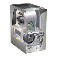
Downflow Application Installation Clearances
Top
Bottom
Left Side Right Side
Top 0
*Front 0
Back 0
Sides 0†
Vent 0
Floor NC‡
*Front clearance in alcove installation must be 24 in. (610 mm).
Maintain a minimum of 24 in. (610 mm) for front service access.
†Allow proper clearances to accommodate condensate trap and
vent pipe installation.
‡
tional base is installed between the furnace and the combustible
floor.
FIGURE 13
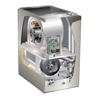
Installation on Non-Combustible Flooring FIGURE 14
1 - Cut oor opening keeping in mind clearances listed
on unit rating plate. Also keep in mind gas supply
connections, electrical supply, ue and air intake
connections and sucient installation and servicing
clearances. See TABLE 1 for correct oor opening
size.
2 - Flange warm air plenum and lower the plenum into
the opening.
3 - Set the unit over the plenum and seal the plenum to
the unit.
4 - Ensure that the seal is adequate.
TABLE 1
NON-COMBUSTIBLE FLOOR OPENING SIZE
Cabinet
Width
Front to Rear Side to Side
in. mm in mm
B (17.5”) 19-3/4 502 16-5/8 422
C (21”) 19-3/4 502 20-1/8 511
NOTE - Floor opening dimensions listed are 1/4 inch (6 mm) larger than
the unit opening. See dimension drawing on page 2.
SUPPLY AIR
PLENUM
PROPERLY
SIZED FLOOR
OPENING
FURNACE
FIGURE 14
Installation on Combustible Flooring FIGURE 15
1 - When unit is installed on a combustible oor,
a downow combustible ooring base must be
installed between the furnace and the oor. The
base must be ordered separately. See TABLE 2 for
opening size to cut in oor.
CAUTION
The furnace and combustible ooring base shall not be
installed directly on carpeting, tile, or other combustible
material other than wood ooring.
 Loading...