Page 11
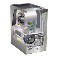
FURNACE
SUPPLY AIR
PLENUM
COMBUSTIBLE
FLOORING BASE
PROPERLY
SIZED FLOOR
OPENING
FIGURE 15
TABLE 2
COMBUSTIBLE FLOORING BASE OPENING SIZE
Cabinet
Width
Catalog
Number
Front to Rear Side to Side
in mm in mm
B (17.5”) 11M60 22 559 18-3/4 476
C (21”) 11M61 22 559 22-3/4 578
2 - After opening is cut, set the combustible ooring
base into opening.
3 - Check berglass strips on the combustible ooring
base to make sure they are properly glued and
positioned.
4 - Lower supply air plenum into the combustible ooring
base until plenum anges seal against berglass
strips.
NOTE - Be careful not to damage berglass strips.
Check for a tight seal.
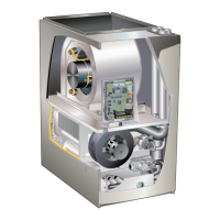
5 - Set the furnace over the plenum.
6 - Ensure that the seal between the furnace and plenum
is adequate.
Installation on Cooling Coil Cabinet FIGURE 16
NOTE - Downow combustible ooring kit is not used.
1 - Refer to reverse-ow coil installation instructions for
correctly sized opening in oor and installation of
cabinet.
2 - When cooling cabinet is in place, set and secure
the furnace according to the instructions that are
provided with the cooling coil. Secure the furnace to
the cabinet.
3 - Seal the cabinet and check for air leaks.
COOLING COIL
PLENUM
PROPERLY
SIZED FLOOR
OPENING
FURNACE
FIGURE 16
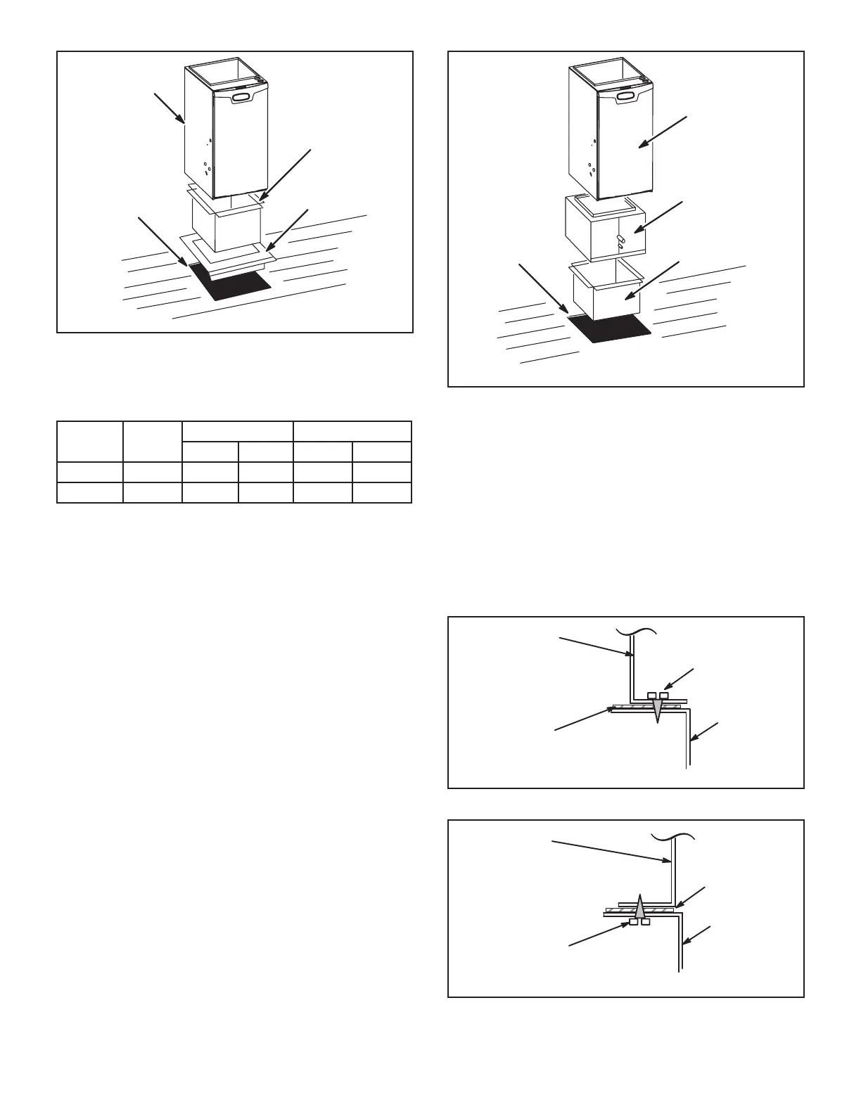
Return Air Opening -- Downow Units
Return air may be brought in only through the top opening
of a furnace installed in the downow position. The follow-
ing steps should be taken when installing plenum:
1 - Bottom edge of plenum should be anged with a
hemmed edge (See FIGURE 17 or FIGURE 18).
2 - Sealing strips should be used to ensure an airtight
seal between the cabinet and the plenum.
3 - In all cases, plenum should be secured to top of
furnace using sheet metal screws.
4 - Make certain that an adequate seal is made.
SECURE FROM
OUTSIDE CABINET
PLENUM
(Field Provided)
SEALING STRIP
(Field Provided)
Side View
CABINET
SIDE PANEL
FIGURE 17
SECURE FROM
INSIDE CABINET
PLENUM
(Field Provided)
SEALING STRIP
(Field Provided)
Side View
CABINET
SIDE PANEL
FIGURE 18
 Loading...