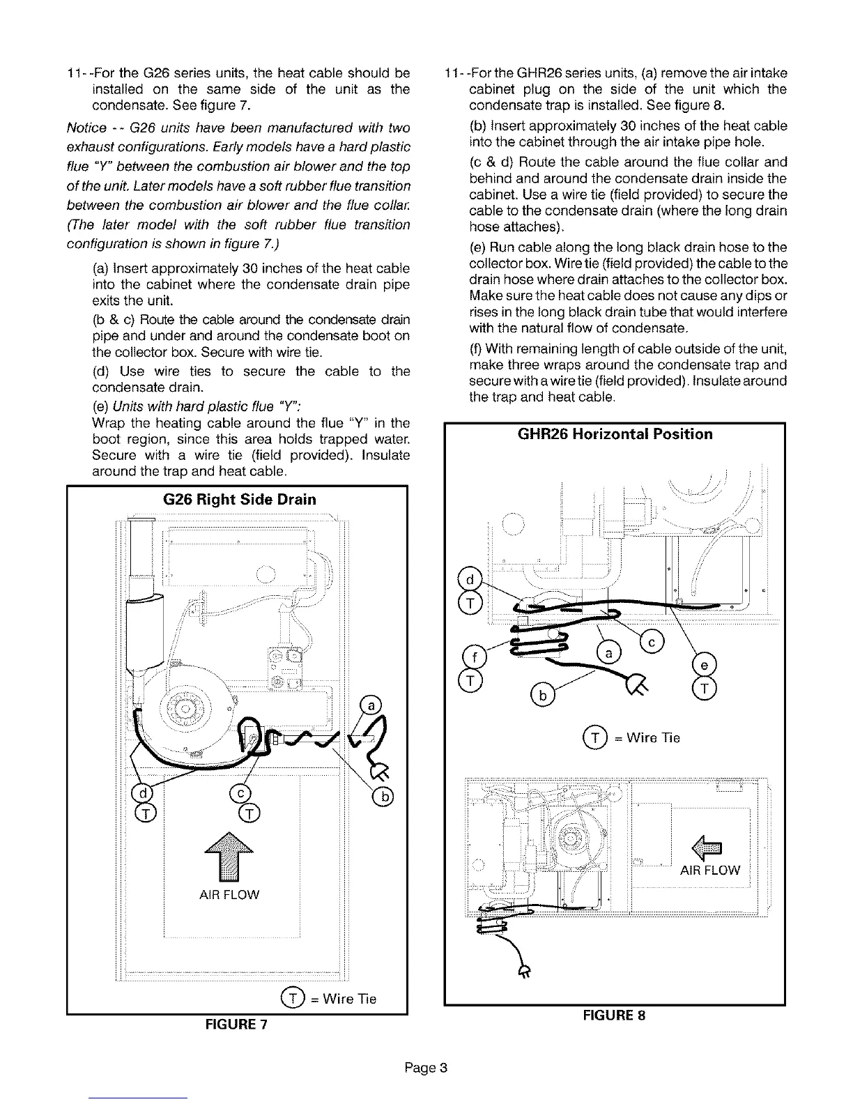
11--FortheG26seriesunits,theheatcableshouldbe
installedon the sameside of the unit as the
condensate.Seefigure7.
Notice -- G26 units have been manufactured with two
exhaust configurations. Early models have a hard plastic
flue °Y° between the combustion air blower and the top
of the unit. Later models have a soft rubber flue transition
between the combustion air blower and the flue collar:
(The later model with the soft rubber flue transition
configuration is shown in figure 7.)
(a) Insert approximately 30 inches of the heat cable
into the cabinet where the condensate drain pipe
exits the unit.
(b & c) Route the cable around the condensate drain
pipe and under and around the condensate boot on
the collector box. Secure with wire tie.
(d) Use wire ties to secure the cable to the
condensate drain.
(e) Units with hard plastic flue °Y°:
Wrap the heating cable around the flue "Y" in the
boot region, since this area holds trapped water.
Secure with a wire tie (field provided). Insulate
around the trap and heat cable.
G26 Right Side Drain
AIR FLOW
Q= Wire Tie
FIGURE 7
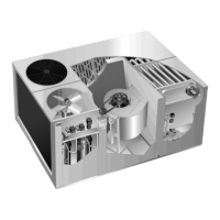
11- -For the GHR26 series units, (a) remove the air intake
cabinet plug on the side of the unit which the
condensate trap is installed. See figure 8.
(b) Insert approximately 30 inches of the heat cable
into the cabinet through the air intake pipe hole.
(c & d) Route the cable around the flue collar and
behind and around the condensate drain inside the
cabinet. Use a wire tie (field provided) to secure the
cable to the condensate drain (where the long drain
hose attaches).
(e) Run cable along the long black drain hose to the
collector box. Wire tie (field provided) the cable to the
drain hose where drain attaches to the collector box.
Make sure the heat cable does not cause any dips or
rises in the long black drain tube that would interfere
with the natural flow of condensate.
(f) With remaining length of cable outside of the unit,
make three wra )s around the condensate trap and
secure with a wire tie (field provided). Insulate around
the trap and heat cable.
GHR26 Horizontal Position
Q= Wire Tie
FIGURE 8
Page 3