2 - After opening is cut, set the additive base into opening.
3 - Check fiberglass strips on additive base to make sure
they are propedy glued and positioned.
4 - Lower supply air plenum into additive base until ple-
num flanges seal against fiberglass strips.
5- Set unit on additive base so unit flanges drop into ple-
num. Refer to figure 8.
NOTE - Be careful not to damage fiberglass strips.
Check for tight seal
C-installation on Cooling Cabinet
1 - Refer to reverse-flow coil installationinstructions for
correctlysized openinginfloorand installationofcabi-
net.
2- When cooling cabinet is in place, installfurnace so
flangesdrop insidecabinetopening.
3 - Seal cabinet and check for air leakage.
Horizontal Applications
The Lennox G24M furnace can be installed in horizontal
applications in either upflow or downflow configuration
(See figure6). It ispreferable toinstalltheunit in the stan-
dard upflow configuration,if possible, because the vent
pipewill not interferewithserviceaccess forblower.Install
two #10 screws in the cabinet bottom (upflow configura-
tion)or cabinet top (downflowconfiguration)to provide a
betterair sea].The unit cannot be installed on its back.
HorizontalApplication
installation Clearances
TOP
SIDE S_DE
BOTI'OM
Vem
Connector
Type
TOP
*FRONT
SACK
SIDES
VENT
FLOOR
Type C
0
2 in. (51 ram)
0
2 in. (51 rnm)
6 in. (152 ram)
0._
Type BI
o
2 in. 151 ram)
0
2 in. (51 ram)
1 in. (25 turn
0"*
*Front clearance in alcove installation must be 24 in.
(610 ram). Maintain a minimum of 24 in, (610 ram) for
front service access,
** For installations on a combustible floor, do not install
the furnace directly on carpeting, tile or other combus-
tible materials other than wood flcorlng.
FIGURE g
Allow for clearancesto combustiblematerials as indicated
on the unit ratingplate. Minimum clearancesfor closet or
alcove installationsare shown infigui'e9.
Furnacesmay be installed in either anatticor a crawispace.
See figure 10 for furnace installationson a platform.
NOTE - When the furnace is installed on a platform in a
crawlspace, it must be elevated enough to avoid water
damage and to allow the air conditioning coil to drain.
Horizontal Application
Unit Installed on Platform
_IOTE-LinecontactispermissibleSeethe unitrating plateforclearances.
_VENT
PIPE
WORKING
pLATFORM
FIGURE 10
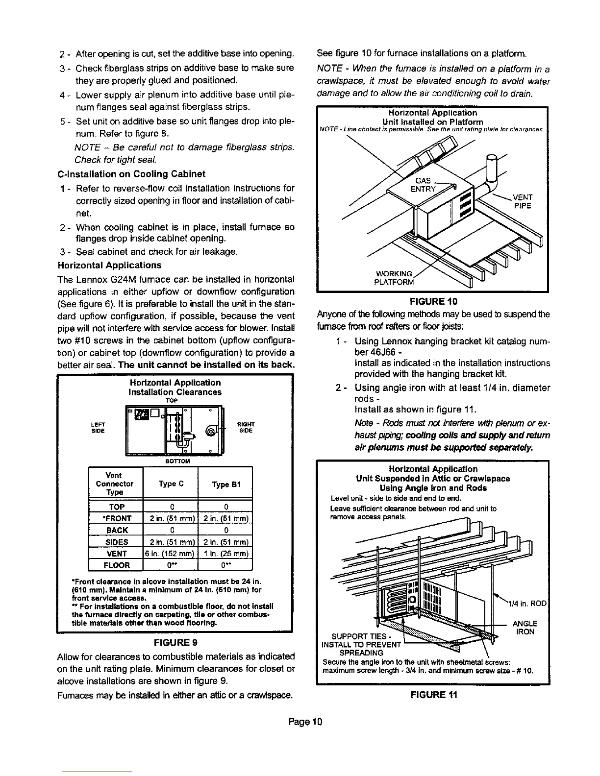
Anyone ofthefollowingmethodsmay be usedtosuspendthe
furnace fiom roofraftersorfloor joists:
1 - Using Lennoxhanging bracket kitcatalog num-
ber46366 -
Install as indicatedin the instaltationinstructions
providedwiththe hangingbracketkit.
2 - Using angle iron with at least 1/4 in. diameter
rods -
Install as shown in figure 11.
Note - Rods must not inter[erav_h plenum or ex-
haustpiping;coolingcoils and supplyand return
air plenums must be supported separately.
FIGURE 11
Page 10
 Loading...


