DownflowApplications
The LennoxG24M furnaceisshippedinthe upflowconfig-
uration and must be converted for downflowinstallation.
Refer tofigure6 and thefollowingstepsto convertthe unit
for downflowinstallation:
1 - Place uniton its backand remove access panel.
2- Disconnect wire harness jackplugs from control
board.
3 - Disconnect sensor lead from control board.
4 - Remove four screws securing cabinet top cap to cabi-
net.
5 - Remove four screws holding heat exchanger assem-
bly in place. Slide heat exchanger out through top of
cabinet.
6 - Rotate heat exchanger 180° and slide back into cabi-
net throughtop. Resecure using four screws.
7 - Remove four screws securing cabinet bottom piece
to cabinet. Replace with cabinet top cap.
8 - Use four screws to install cabinet bottom piece where
cabinet top was.
9 - Reconnect sensor lead to control board.
10- Reconnectwire harness jackptugs to control board.
11- Replace unit access panel.
12- Use cord clip located on right side of furnace to
hold wiring away from hot surfaces in heating
compartment. Install two #10 sheet metal screws in
cabinet top to provide a better air seaL
Indownflowapplications,the unitcanbe installedinthree dif-
ferent ways: on non-combustibleflooring, on combustible
floor usingan additivebase, oron a reverse-flow coolingcab-
inet. Do not drag unit across floor.
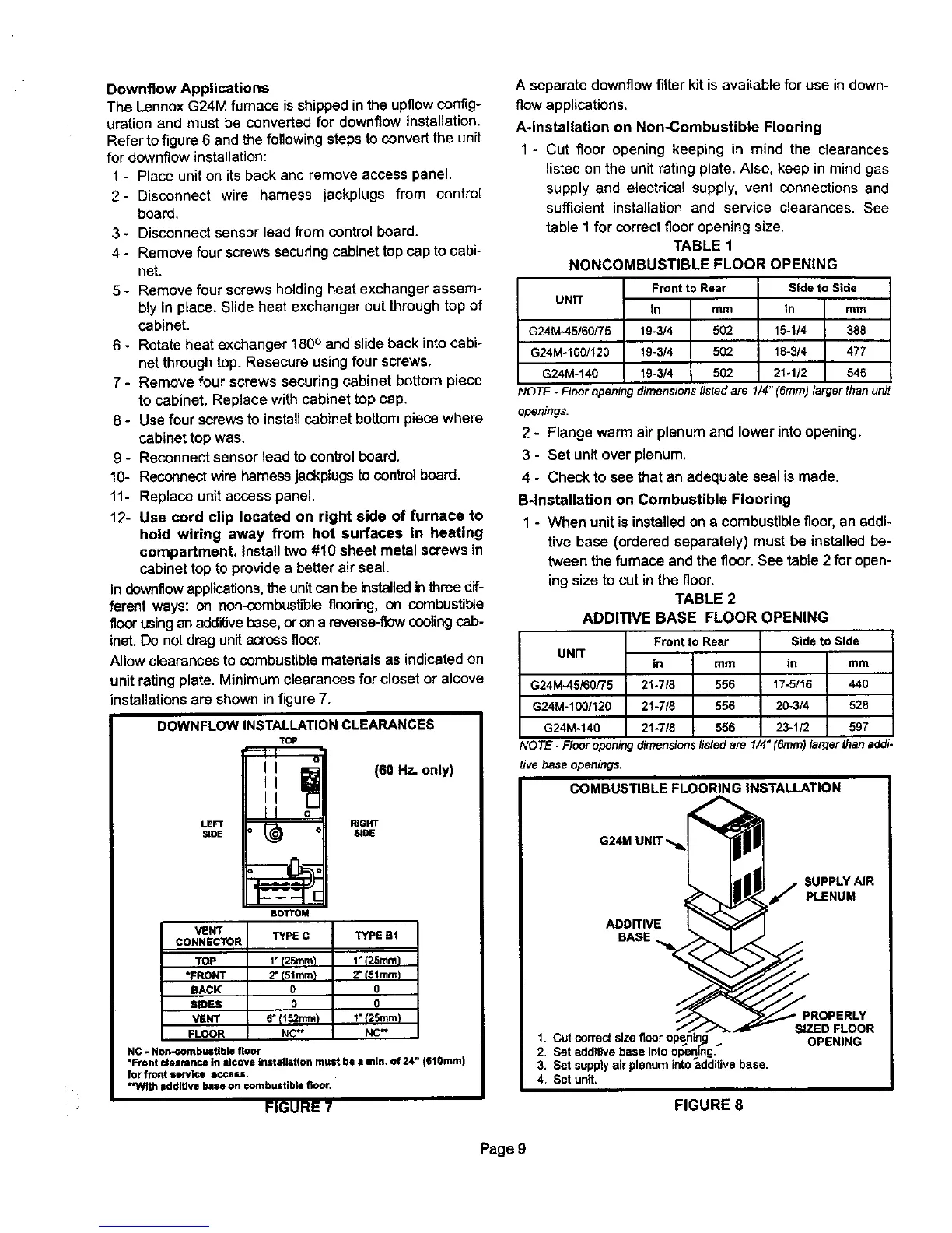
Allow clearances to combustible materials as indicated on
unit rating plate. Minimum clearances for closet or alcove
installations are shown in figure 7.
DOWNFLOWINSTALLATIONCLEARANCES
TOP
(60 Hz. only)
LEFT RIGHT
SIDE SiDE
BOTTOM
VENT TYPE C TYPE Bt
CONNECTOR
TOP 1"I25mm_ 1* 125mint
•FRONT 2"I51mm) 2" t81mm)
BACK 0 0
SIDES 0 0
VENT 6" {r 52rnm'p I" t25mrn_
FLeeR NC" NC"
NC - Non-combustible floor
"Front clearance In Ilcove Install_tion must be • nlln. of 24" (610rnm)
for front service IOCaKK.
"With addiUve base on combustible floor.
FIGURE 7
A separate downflow filter kit is available for use in down-
flow applications.
A*lnstallation on Non-Combustible Flooring
1 - Cut floor opening keeping in mind the clearances
listedonthe unit rating plate. Also, keep in mindgas
supply and electrical supply, vent connections and
sufficient installationand service clearances. See
table 1for correct flooropening size.
TABLE 1
NONCOMBUSTIBLE FLOOR OPENING
G24M*45/60/75
G24M-1001120
G24M-140
Front to Rear
UNIT
In mm
19-3/4 502
19-3/4 502
19-3/4 502
Side to Side
In mm
15-1/4 388
18-3/4 477
21÷1/2 546
COTE- Flooropeningdimensionslistedare1/4"(6rnm) larger than unit
openings.
2 - Flange warm air plenumand lower intoopening.
3 - Set unitover plenum.
4 - Check to see that an adequate sealis made.
B4nstallation on Combustible Flooring
1 - When unit isinstalledon a combustiblefloor,an addi-
tive base (ordered separately) must be installedbe-
tween the furnace and the floor. See table 2 for open-
ing size to cut in the floor.
TABLE 2
ADDITIVE BASE FLOOR OPENING
UNIT
G24M-45/60/75
G24M-100/120
G24M.140
Front to Rear
in rnm
21-7/8 556
21-718 556
21-718 556
Side to Side
in mm
17-5/t6 440
20-3/4 528
23-1/2 597
NO TE - Floor opening dimensionslistedare 1/4" (6ram) larger than addi-
tive base openings.
COMBUSTIBLE FLOORING INSTALLATION
G24M
ADDITIVE
BASE
SUPPLY AIR
_" PLENUM
1. Cut correct size floor _:
2. Set additive base intoopening._
3. Set supply air plenum into additive base.
4. Set unit,
FIGURE 8
SIZED FLOOR
OPENING
Page 9
 Loading...


