ii i i ii ii ; il; = iiiiiiiiiiil
The Lennox G24M multi-position gas furnace can be
installed as shipped in upflow or horizontal position with
right-hand or left-hand discharge. The furnace can easi-
ly be converted for downflow applications.
Select a location that allows for required clearances
listed on the unit rating plate. Also consider gas supply
connections, electrical supply, vent connection and
installation and service clearances [24 inches (610 mm)
at unit front].
NOTE - 1/3and 1/2hp blowermotors are equipped with ei-
ther four flexible mounting legs or three flexible legs and
one rigid leg. The dgid leg is equipped with a shipping bolt
and a flat white plastic washer (rather than the rubber
mounting grommet used witha flexible mounting leg). This
shipping bolt and flat washer must be removed before the
furnace is put into operation. Once the shippingbolt and
washer are removed, the rigid leg will not touch the fan
housing.
Upflow Applications
The LennoxG24M furnace is shipped in a standardupflow
position.Level_ furnaceusing shimsor levelingbolts. Four
knockoutsinthefumaca b_sepanelarefactory-providedfor
the installationof levelingbolts (field-provided).Allow for
clearancesto combustiblematerialsas indicatedon the unit
ratingplate.Minimumclearancesfor closetoralcove installa-
tionsare shownin figure5.
In upfiowapplications, returnair can be broughtin through
the bottom or either side of the furnace. If a furnace with
bottomreturnair isinstalledona platform,make an airtight
sealbetween the bottomofthe furnaceand the platformto
ensureproperand safe operation.
Knockouts areprovided on both sidesof thefurnace cabi-
net for installations with side return air.When side return air
is used, seal the bottom ofthe furnace using the panel pro-
vided.
An upflow filter rack is available and must be ordered sepa-
rately. The adjustable rack can be installed beneath the fur-
nace (flush with cabinet edges) for bottom return air ap-
)lications or on theside of the furnace for side return air.
Upflow Application
Installation Clearances
LEFT
SIDE
TOP
BOTTOM
RIGHT
S;DE
1 in. t'25 ram) 1In. (25 mm_ I
2in.(51mm) 2in.(51mm}]
0 0
0 o
6in.(152mm) 1in.(25mm}i
0" 0"
*Front clearance in alcove Installation must be 24 in. (610
ram). Maintain a minimum of 24 in. (610 rnm) for front service
eccess.
*" For installations on a combustible floor, do not install the
furnace directly on carpeting, tile or other combustible mate-
rials other than wood flooring=
Vent
Connector Type C Type BI
Twe
TOP
*FRONT
BACK
SIDES
VENT
FLOOR
FIGURE 5
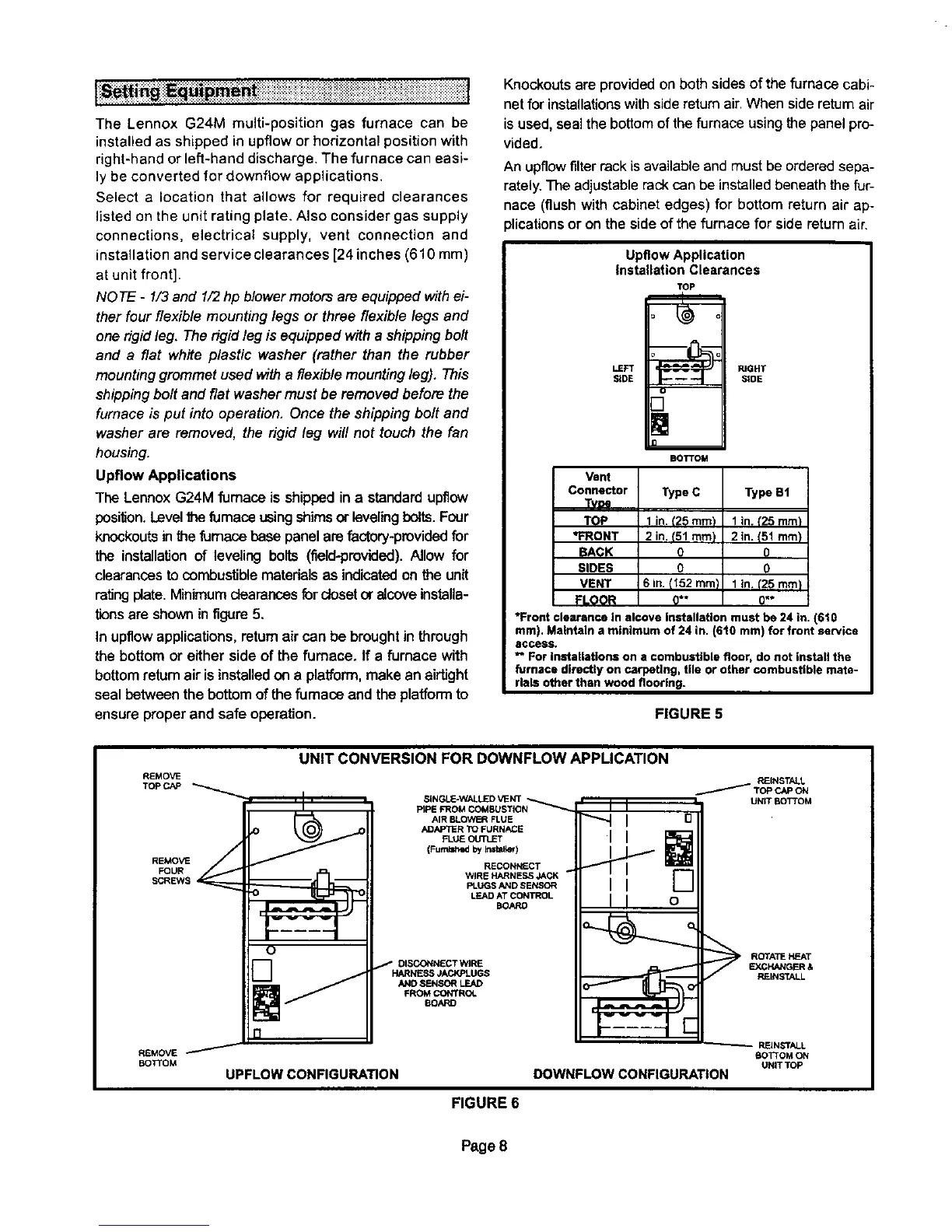
REMOVE
TOPCAP
REMOVE
FOUR
SCREWS
REMOVE
BOTTOM
UNIT CONVERSION FOR DOWNFLOW APPLICATION
SINGLE-WALLED VENT ,,.._.,..,._._
PtPE FROM COMBUSTION
AIR BLOWER FLUE
ADAPTER TO FURNACE
FLUIE OUTLET
(FumW_ed by Imta_eq
RECONNECT
WIRE HARNESS JACK
PLUGS AND SENSOR
LEAD AT CONTROL
BOARD
DISCONNECT WIRE
HARNESS JACKPLUGS
AND SENSOR LEAD
FROM CONTROL
8OARD
UPFLOW CONFIGURATION
' I I
I I o
PJEINSTALL
/ Topc,,.-oN
UNIT BOTTOM
ROrATE HEATEXCHANGER &
REINSTALL
_-- REIN_rALL
BOTTOM ON
UNIT TOP
DOWNFLOWCONFIGURATION
FIGURE 6
Page 8
 Loading...


