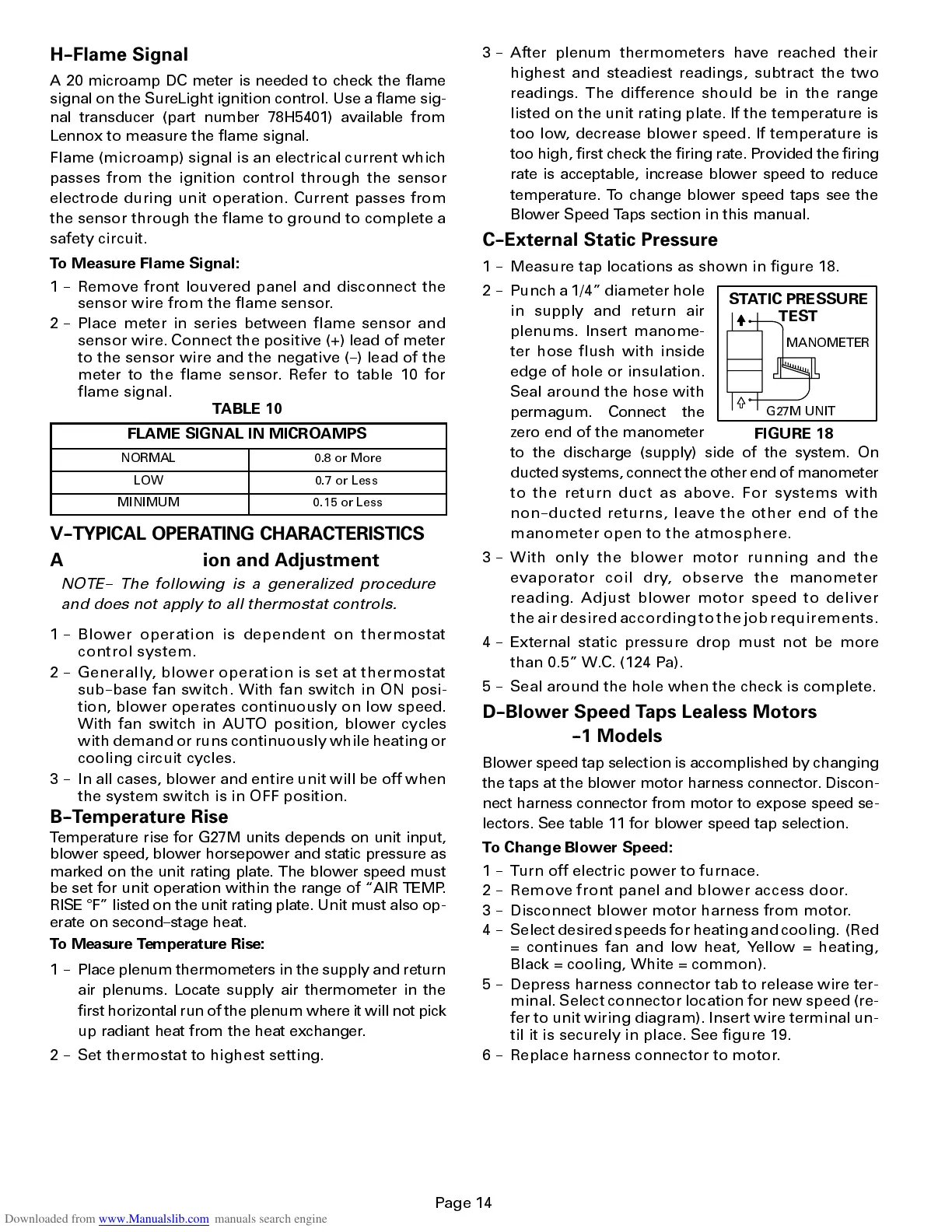
FIGURE 18
STATIC PRESSURE
TEST
MANOMETER
G27M UNIT
Page 14
H--Flame Signal
A 20 microamp DC meter is needed to check the flame
signal on the SureLight ignition control. Use a flame sig-
nal transducer (part number 78H5401) available from
Lennox to measure the flame signal.
Flame (microamp) signal is an electrical current which
passes from the ignition control through the sensor
electrode during unit operation. Current passes from
the sensor through the flame to ground to complete a
safety circuit.
To Measure Flame Signal:
1 -- Remove front louvered panel and disconnect the
sensor wire from the flame sensor.
2 -- Place meter in series between flame sensor and
sensor wire. Connect the positive (+) lead of meter
to the sensor wire and the negative (--) lead of the
meter to the flame sensor. Refer to table 10 for
flame signal.
TABLE 10
FLAME SIGNAL IN MICROAMPS
NORMAL 0.8 or More
LOW 0.7 or Less
MINIMUM 0.15 or Less
V--TYPICAL OPERATING CHARACTERISTICS
A--Blower Operation and Adjustment
NOTE-- The following is a generalized procedure
and does not apply to all thermostat controls.
1 -- Blowe r o perati on is de penden t on t hermos tat
cont rol sys tem.
2 -- Gener ally, blowe r operat ion is s et at t hermos tat
sub--base fan switch. With fan switch in ON posi-
tion, blower operates continuously on low speed.
With fan switch in AUTO position, blower cycles
with demand or runs continuously while heating or
cooling circuit cycles.
3 -- In all cases, blower and entire unit will be off when
the system switch is in OFF position.
B--Temperature Rise
Tempera ture rise for G27 M units depends on unit input,
blower speed, blower horsepo wer and stat ic pressure as
marked on the unit rating plate. The blower speed must
be set for unit operati on within the range of AIR TEMP.
RISE
q
F listed on the unit rating plate. Unit must also op-
erate on second--stage heat.
To Measure Tempera ture Rise:
1 -- Place plenum thermo mete rs in the supply and return
air plenums. Locate supply air thermom eter in the
first horizontal run of the plenum where it will not pick
up radiant heat from the heat exchanger.
2 -- Set thermostat to highest setting.
3 -- After plenum thermometers have reached their
highest and steadiest readings, subtract the two
readings. The difference should be in the range
listed on the unit rating plate. If the temperature is
too low, decrease blower speed. If temperature is
too high, first check the firing rate. Provided the firi ng
rate is acceptab le, increase blower spee d to reduce
tempera ture. To change blower speed taps see the
Blower Speed Taps section in this manual.
C--External Static Pressure
1 -- Measure tap locations as shown in figure 18.
2 -- Punch a 1/4 diameter hole
in supply and return air
plenums. Insert manome-
ter hose flush with inside
edge of hole or insulation.
Seal around the hose with
permagum . Connect the
zero end of the manometer
to the discharge (supply) side of the system. On
ducted systems, connect the other end of manometer
to t he ret urn duct as abo ve. Fo r sys tems with
non--duc ted returns , leav e the ot her end of the
manomete r op en to t he atmos phe re.
3 -- Wit h on ly t he b lower mo tor runni ng and the
evaporat or c oi l dr y, obs erve the mano meter
readin g. A djus t b lower motor sp eed to deliv er
theairdesiredaccordingtothejobrequirements.
4 -- External static pressure drop must not be more
than 0.5 W.C. (124 Pa).
5 -- Seal around the hole when the check is complete.
D--Blower Speed Taps Lealess Motors
--1 Models
Blower speed tap selection is accomplished by changing
the taps at the blower motor harness connector . Discon-
nect harness connector from motor to expose speed se-
lectors. See table 11 for blower speed tap selection.
To Change Blower Speed:
1 -- Turn off electric power to furnace.
2 -- Remove front panel and blower acc ess door.
3 -- Disconnect blower motor harness from motor.
4 -- Select desired speeds for heating and cooling. (Red
= continues fan and low heat, Yellow = heating,
Black = cooling, White = common).
5 -- Depress harness connector tab to release wire ter-
minal. Select connector location for new speed (re-
fer to unit wiring diagram). Insert wire terminal un-
til it is securely in place. See figure 19.
6 -- Replace harness connector to motor.
 Loading...


