Page 24
Condensate Piping
This unit is designed for either right or leftside exit of con
densate piping. Condensate drain line should be routed
only within the conditioned space to avoid freezing of con
densate and blockage of drain line. An electric heat cable
should be used where condensate drain is exposed to un
conditioned areas. The following procedure is for all G32
units.
1 − Determine which side condensate will exit the unit.
2 − Connect 1/2" (13mm) plastic pipe plug (provided) in
the unused end of the condensate trap. Install plug so
that it is sealed water tight yet able to be removed. Do
not permanently seal the connection. Teflon tape is
recommended to seal joint. See figure 34.
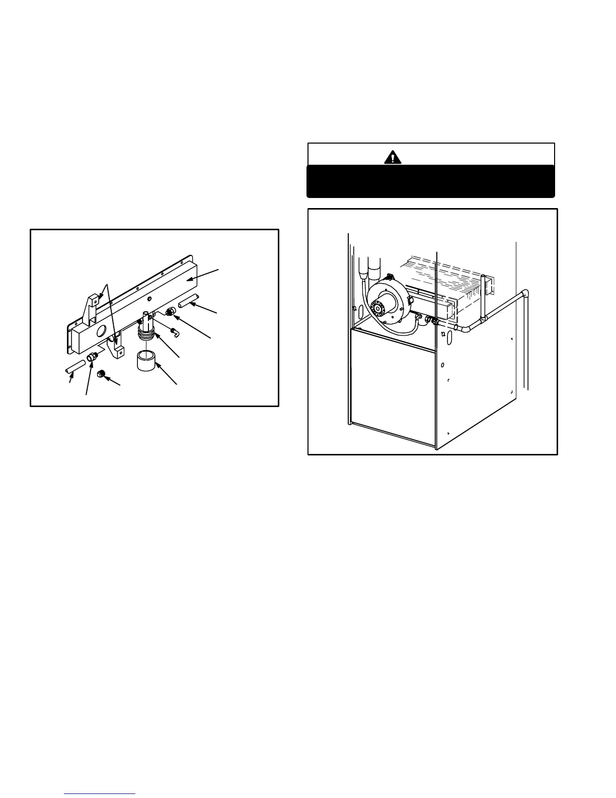
CONDENSATE ASSEMBLY
(For left or right installation)
FIGURE 34
COLD HEADER
BOX
NIPPLE
ADAPTER
ADAPTER
NIPPLE
PLUG
BOOT OR CAP
COMBUSTION AIR
BLOWER BRACKET
CONDENSATE TRAP
3 − Use the provided adapter (1/2" PVC x 1/2" MPT) and
the nipple (1/2" PVC) to carry drainage outside the
cabinet. If a field substitute is needed, 1/2" CPVC x
1/2" MPT adapter and 1/2" CPVC is acceptable for
use.
4 − Glue nipple to the adapter using the procedures out
lined in the Joint Cementing Procedures" section.
The nipple/adapter assembly should be connected in
a nonpermanent manner and must be water tight.
Teflon tape is recommended to seal the joint.
For RightHand Side Condensate Exit:
Install the nipple/adapter assembly from the outside
of the cabinet and insert the adapter into the threaded
opening in the condensate trap.
For LeftHand Side Condensate Exit:
Insert nipple/adapter assembly from the left hand
side of the cabinet and through the combustion air
blower mounting structure into the threaded opening
in the condensate trap.
5 − Connect field supplied plumbing to nipple and route to
open drain. Plumbing should be vented to a point higher
than the condensing coil. See figure 35.
CAUTION
Do not use copper tubing or existing copper
condensate lines for drain line.
FIGURE 35
CONDENSATE PLUMBING
(Plumbing must be vented higher than coil.)
6 − Connect condensate drain line (1/2" [13mm] SDR 11
plastic pipe or tubing) to condensate connection on
drip leg assembly and route to open drain. Conden
sate line must be sloped downward away from drip leg
to drain. If drain level is above drip leg, condensate
pump must be used to condensate line. Condensate
drain line should be routed within the conditioned
space to avoid freezing of condensate and blockage of
drain line. If this is not possible, a heat cable kit may be
used on the condensate drip leg and line. Heating
cable kit is available from Lennox in various lengths;
6ft. (1.8m) − kit no. 18K48; 24ft. (7.3m) − kit no. 18K49;
and 50ft. (15.2m) − kit no. 18K50.

 Loading...


