Page 15
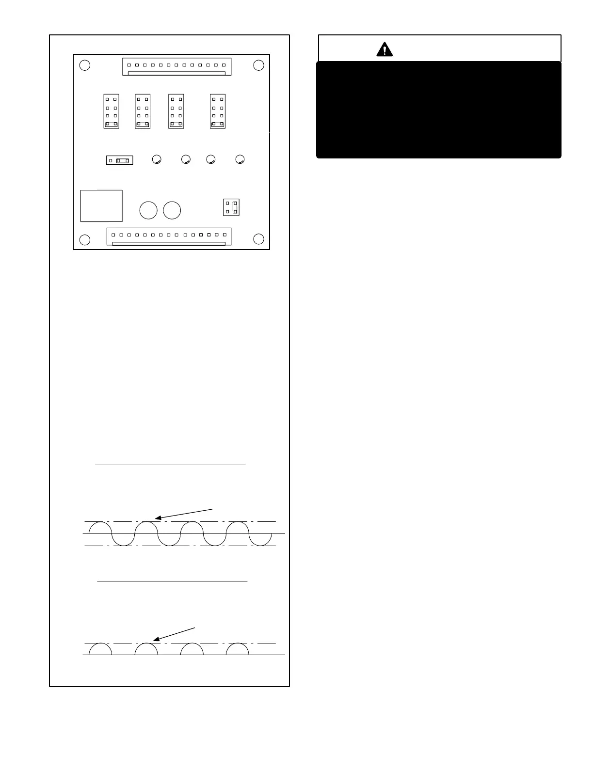
VSP2−1 BLOWER CONTROL BOARD (A24)
VOLTAGES INTO VSP2−1
VOLTAGES FROM VSP2−1 TO ELECTRONICALLY
CONTROLLED BLOWER MOTOR
34 volts
−34 volts
0
volts
Voltage across J73 pins 13 to 1 and 6 to 1 is 24VAC as shown here.
Refer to unit wiring diagram.
Voltage across J46 pins 6 to 3 and 1 to 3 is half-rectified AC as shown here.
Refer to unit wiring diagram.
Voltage across J73 pins 4 to 1 is approximately 15-20VDC (straight voltage)
if CCB is used. If Harmony is used a voltage of 0−25VDC should be present.
If CCB or Harmony is not used, pin 4 to 1 voltage is 21VAC.
Approx.
34 volts
0
volts
Voltage across J46 pins 8 and 9 to 3, is approximately 15-20VDC if CCB is used. If
CCB or Harmony is not used, pins 8 and 9 to 3 voltage is approximately 21VAC. If
Harmony is used a voltage of 0−25VDC should be present.
24VAC @ 60Hz.
24VAC Half-Rectified (DC
Pulse)
@ 60Hz.
J46
HIGH LOW ADJUST HEAT
CFM
HI/LOW
ON/OFF
HEAT
HTG.
BLOWER
12
DS2
DS3
DS1
DS4
1
2
3
4
1
2
3
4
1
2
3
4
TEST
−
+
NORM
210
150
90
270
J73
1
1
J73
PIN 1 - C - 24 VAC common.
PIN 2 - G - Input signal from thermostat’s fan signal.
PIN 3 - W2 - Input signal for second stage heat from the thermostat.
PIN 4 - DS - Input signal for the blower speed regulation.
PIN 5 - Limit - Input signal from the external limit.
PIN 6 - R - 24 VAC power to the thermostat.
PIN 7 - C - 24 VAC common.
Pin 8 - C - 24 VAC common.
PIN 9 - CI - Input signal from the fan limit control.
PIN 10 - CO - Output signal to the burner control.
PIN 11 - HT - Input signal from the fan limit control.
PIN 12 - ACC - 24 VAC accessory output.
PIN 13 - 24V - Input 24 VAC power for the VSP2-1.
PIN 14 - 24V - Input 24 VAC power for the VSP2-1.
PIN 15 - V - Input signal from the gas line.
J46
PIN 1 - Heat - Heat speed input signal to the ICM2 motor.
PIN 2 - C - 24 VAC common.
PIN 3 - C - 24 VAC common.
PIN 4 - High Tap - High Speed programming input.
PIN 5 - Low Tap - Low speed programming input.
PIN 6 - On / Off - On / off output signal to the ICM2 motor.
PIN 7 - Adjust Tap - ICM2 mode selection.
PIN 8 - Hi / Low - Speed regulate input signal to the ICM2 motor.
PIN 9 - Hi / Low - Speed regulate input signal to the ICM2 motor.
PIN 10 - Ref. V - ICM2 reference voltage.
PIN 11 - Heat Tap - Heating blower speed programming.
PIN 12 - C - 24 VAC common.
PIN 13 - cfm - Motor speed diagnostic signal.
FIGURE 12
IMPORTANT
24 VAC half wave rectified (DC pulse), when
measured with a meter, may appear as a lower
or higher voltage depending on the make of the
meter. Rather than attempting to measure the
output voltage of A24, see G32V BLOWER &
VSP2 BLOWER CONTROL BOARD TROUBLE-
SHOOTING FLOW CHART in the TROUBLE-
SHOOTING section of this manual.
Diagnostic LED Lights
a − DS3 ON/OFF"
ON/OFF−DS3 indicates there is a demand for the blower motor
to run. When the ON/OFF LED−DS3 is lit, a demand is being
sent to the motor. In heating mode only, there is a 45 second
fan ON" delay in energizing ON/OFF LED−DS3. The
light will not go off until adjustable fan OFF" delay has
expired.
If ON/OFF LED−DS3 is on and both HIGH/LOW LED−DS1 &
HEAT LED−DS2 are off, the motor will operate in low
speed.
b − DS2 HEAT"
If HEAT LED−DS2 is on, the blower is running in the heat
speed according to the HEAT" jumper setting. The HEAT
LED−DS2 comes on instantaneous and switches off when
the call for heat is satisfied.
NOTE−When the blower is in OFF" delay mode, the mo-
tor runs at low speed, therefore the HEAT LED−DS2 is off. It
switches off when the call for heat is satisfied.
c − DS1 HI/LOW"
HIGH/LOW LED−DS1 indicates whether the blower is oper-
ating in high or low speed. When the light is off, the blower is
running in low speed according to the LOW" jumper set-
ting. When HIGH/LOW LED−DS1 is on, the blower is oper-
ating in high speed according to the HIGH" jumper setting.
d − DS4 CFM"
CFM LED−DS4 indicates the CFM the unit is operating, ac-
cording to the jumper settings. The light flashes once for
approximately every 100 CFM. For example, if the unit is
operating at 1000 CFM, CFM LED−DS4 will flash 10 times.
If the CFM is 2050, CFM LED−DS4 will flash 20 full times
plus one fast or half flash.
At times the light may appear to flicker or glow. This takes
place when the control is communicating with the motor be-
tween cycles. This is normal operation.
The appropriate speed according to application and CFM
need is selected by moving jumper pins.

 Loading...


