DIGITAL
SCALE
OUTOOOR
UNIT
TEMPERAYURI;;
SENSOR
(LIQUID
LINE)
c.
TO
L1QUIO
LINE
SERVICE
VALVE
Ct1ARGE
IN
LIQUID
PHASE
GAUGE
SET
MANIFOLD
GAUGe
seT
CONNECTIONS
FOR
TESTING
AND
CHARGING
B
SUCTION
LINE
SERVICE
PORT
CONNECTION
o
TEMP~RAiURE
SENSOR
A
CI0611
manifold
gauge
set
valves
and
COnl'llilct
Ihll
center
hose
to
a cyllndllr
of
HFC-410A.
Set
fur
liquid
phase
charging.
B
Connect
the
manlrold
gauge
lIe!'5
low
pressure
side
10
the
Gucllon
line
servicll
port
C
Connect
the
manifold
gause
oet'B
high
pressure
side
10
ltIe
liqvid
fine
service
part.
o
Position
IamporQlure
Bensor
on
liquid
line
nllAr
liquid
linll
service
part
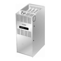
Figure 12. Gauge Set Setup and
Connections
~:;:ru;;iiiID:~:::T.'I!'I':"I::::~'i'l'mA'lm':===~mr.lm~IT'ri'mrnr.rr=;T.;,1!i1
3.
After evacuation is complete, open the liquid line and
If the outdoor unit is void
of
refrigerant, clean the system
using the procedure described below.
1,
Leak check system using procedure outlined
in
figure
10.
2,
Evacuate the system using procedure outlined in
figure
11.
3,
Use nilrogen to break the vacuum and install a new
filter drier in the system.
4. Evacuate the system again using procedure outlined
on
figure 11,
5.
Weigh
in
refrigerant using procedure outlined under
figure
15.
A IMPORTANT
rr
WIlli'}
octUippecl Wlttl d
c.r;lllk'~Cl?e
lleater,lt
~.tl(J\llcI
bo
ener9lzt:rj
~4
hours betorp. IJlIII
~;lml-up
10
pr~v~rJl
cOfllpre';sor
CJ.illl,IUI.~
U',;
<I
I
G~.lIlt
(It
~.lu<JUIf1!l.
1,
Rotate fan to check for binding.
2.
Inspect all faclory- and field·lnstalled wiring for loose
connections.
suction line service valves to release the refrigerant
charge (contained in outdoor unit) into the system.
4. Replace the stem caps and tighten as specified in
Operating Service Valves on page
7.
5.
Check voltage supply at the disconnect switch. The
voltage must be within
lhe
range listed on the unit's
nameplate.
If not, do not slart the equipment until you
have consulted with the power company and the
voltage condition has
been
corrected.
6.
Set the thermostat for a cooling demand. Turn on
power to the indoor indoor unit and close the outdoor
unit disconnect switch to start the unit.
7.
Recheck voltage while the unit is running. Power must
be within range shown
011
the nameplate.
8. Check system for sufficient refrigerate using the
procedures thai follow.
ThiS
section outlines procedures for:
1.
Connecting gauge set for testing and charging;
2.
Checking and adjusting indoor
air1low:
3.
Adding
or
removing refrigerant.
Page
21
13"CX
SERIES
6
~
.d
6VL8
'Ol~
3#t.~_

 Loading...