G60UHVunitsareequippedwitha two-stage,variable
speedintegratedcontrol.Thiscontrolmanagesignition
timing,heatingmodefan offdelaysandindoorblower
speedsbasedonselectionsmadeusingthecontroldip
switchesandjumpers.Thecontrolincludesan internal
watchguardfeaturewhichautomaticallyresetstheignition
controlwhenithasbeenlockedout.Afteronehourofcon-
tinuousthermostatdemandforheat,thewatchguardwill
breakandremakethermostatdemandtothefurnaceand
automaticallyresetthecontroltorelightthefurnace.
HeatingOperationDIPSwitchSettings
Switch1 -- ThermostatSelection-- Thisunitmaybe
usedwitheithera single-stageor two-stagethermostat.
ThethermostatselectionismadeusingaDIPswitchwhich
mustbeproperlypositionedfortheparticularapplication.
TheDIPswitchis factory-positionedforusewitha two-
stagethermostat.Ifasingle-stagethermostatistobeused,
theDIPswitchmustberepositioned,
a- Select "OFF" for two-stage heating operation con-
trolled by a two-stage heating thermostat (factory set-
ting);
b- Select "ON" for two-stage heating operation con-
trolled by a single-stage heating thermostat, This set-
ting provides a timed delay before second-stage heat
is initiated,
Switch 2 -- Second Stage Delay (Used with Single-
Stage Thermostat Only) -- This switch is used to deter-
mine the second stage on delay when a single-stage ther-
mostat is being used. The switch is factory-set in the OFF
position, which provides a 10-minute delay before second-
stage heat is initiated, If the switch is toggled to the ON
position, it will provide a 15-minute delay before second-
stage heat is initiated, This switch is only activated when
the thermostat selector jumper is positioned for SINGLE-
stage thermostat use,
Switches 3 and 4 -- Blower-Off Delay -- The blower-on
delay of 45 seconds is not adjustable. The blower-off delay
(time that the blower operates after the heating demand
has been satisfied) can be adjusted by moving switches 3
and 4 on the integrated control board, The unit is shipped
from the factory with a blower-off delay of 90 seconds, The
blower off delay affects comfort and is adjustable to satisfy
individual applications. Adjust the blower off delay to
achieve a supply air temperature between 90° and 110°F at
the exact moment that the blower is de-energized. Longer
off delay settings provide lower supply air temperatures;
shorter settings provide higher supply air temperatu-
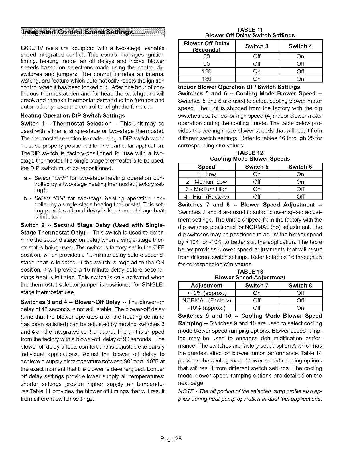
res,Table 11 provides the blower off timings that will result
from different switch settings,
TABLE 11
Blower Off Delay Switch Settings
Blower Off Delay Switch 3 Switch 4
(Seconds)
60 Off On
90 Off Off
120 On Off
180 On On
Indoor Blower Operation DIP Switch Settings
Switches 5 and 6 -- Cooling Mode Blower Speed --
Switches 5 and 6 are used to select cooling blower motor
speed. The unit is shipped from the factory with the dip
switches positioned for high speed (4) indoor blower motor
operation during the cooling mode. The table below pro-
vides the cooling mode blower speeds that will result from
different switch settings. Refer to tables 16 through 25 for
corresponding cfm values,
TABLE 12
Cooling Mode Blower Speeds
Speed Switch 5 Switch 6
1 - Low On On
2 - Medium Low Off On
3 - Medium High On Off
4 - High (Factory) Off Off
Switches 7 and 8 -- Blower Speed Adjustment --
Switches 7 and 8 are used to select blower speed adjust-
ment settings. The unit is shipped from the factory with the
dip switches positioned for NORMAL (no) adjustment, The
dip switches may be positioned to adjust the blower speed
by +10% or -10% to better suit the application, The table
below provides blower speed adjustments that will result
from different switch settings. Refer to tables 16 through 25
for corresponding cfm values,
TABLE 13
Blower Speed Adjustment
Adjustment Switch 7 Switch 8
+10% (approx,) On Off
NORMAL (Factory) Off Off
-10% (approx,) Off On
Switches 9 and 10 -- Cooling Mode Blower Speed
Ramping -- Switches 9 and 10 are used to select cooling
mode blower speed ramping options, Blower speed ramp-
ing may be used to enhance dehumidification perfor-
mance. The switches are factory set at option A which has
the greatest effect on blower motor performance. Table 14
provides the cooling mode blower speed ramping options
that will result from different switch settings, The cooling
mode blower speed ramping options are detailed on the
next page,
NOTE - The off portion of the selected ramp profile also ap-
plies during heat pump operation in dual fuel applications,
Page 28

 Loading...


