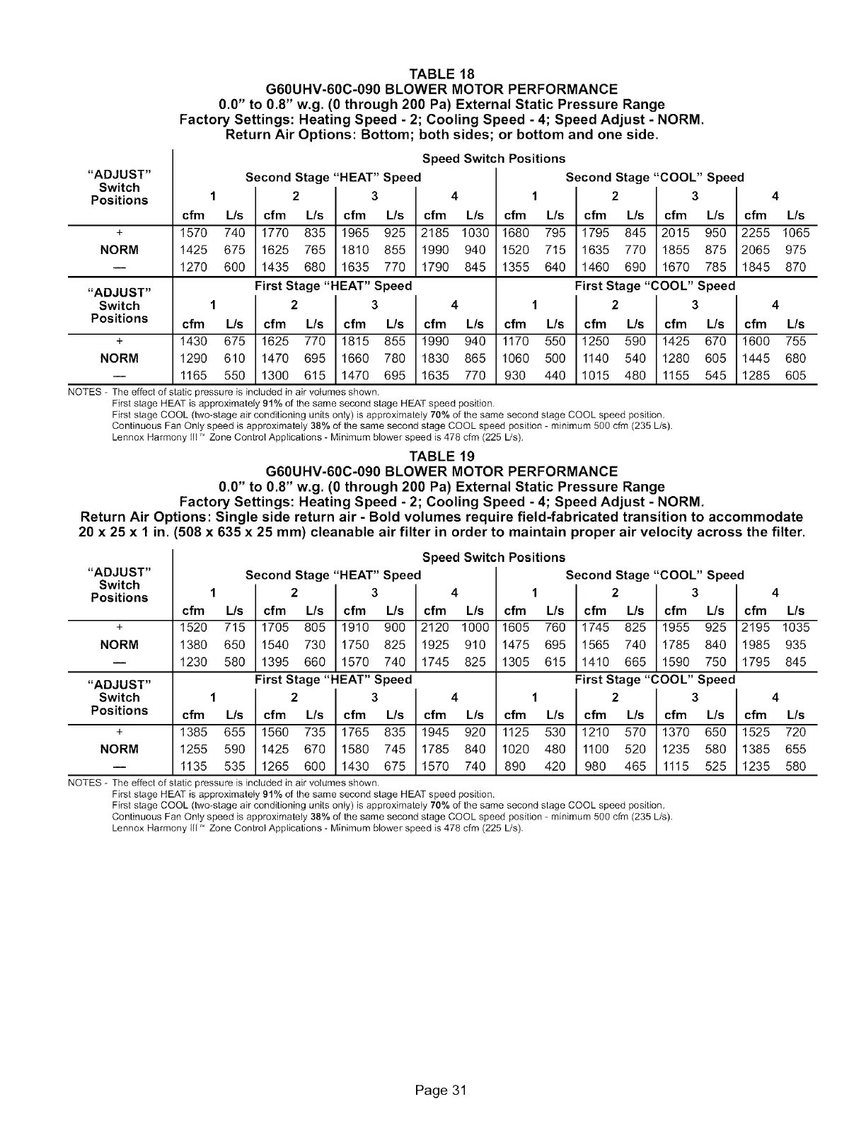
TABLE 18
G60UHV-60C-090 BLOWER MOTOR PERFORMANCE
0.0" to 0.8" w.g. (0 through 200 Pa) External Static Pressure Range
Factory Settings: Heating Speed - 2; Cooling Speed - 4; Speed Adjust - NORM.
Return Air Options: Bottom; both sides; or bottom and one side.
"ADJUST"
Switch
Positions
Speed Switch Positions
Second Stage "HEAT" Speed Second Stage "COOL" Speed
1 2 3 4 1 2 3 4
cfm L/s cfm L/s cfm L/s cfm L/s cfm L/s cfm L/s cfm L/s cfm L/s
+ 1570 740 1770 835 1965 925 2185 1030 1680 795 1795 845 2015 950 2255 1065
NORM 1425 675 1625 765 1810 855 1990 940 1520 715 1635 770 1855 875 2065 975
-- 1270 600 1435 680 1635 770 1790 845 1355 640 1460 690 1670 785 1845 870
"ADJUST" First Stage "HEAT" Speed First Stage "COOL" Speed
Switch 1 2 3 4 1 2 3 4
Positions cfm L/s cfm L/s cfm L/s cfm L/s cfm L/s cfm L/s cfm L/s cfm L/s
+ 1430 675 1625 770 1815 855 1990 940 1170 550 1250 590 1425 670 1600 755
NORM 1290 610 1470 695 1660 780 1830 865 1060 500 1140 540 1280 605 1445 680
-- 1165 550 1300 615 1470 695 1635 770 930 440 1015 480 1155 545 1285 605
NOTES - The effect of static pressure is included in air volumes shown.
First stage HEAT is approximately 91% of the same second stage HEAT speed position.
First stage COOL (two-stage air conditioning units only) is approximately 70% of the same second stage COOL speed position.
Continuous Fan Only speed is approximately 38% of the same second stage COOL speed position - minimum 500 cfm (235 L/s).
Lennox Harmony Ill ' Zone Control Applications - Minimum blower speed is 478 cfm (225 Us).
TABLE 19
G60UHV-60C-090 BLOWER MOTOR PERFORMANCE
0.0" to 0.8" w.g. (0 through 200 Pa) External Static Pressure Range
Factory Settings: Heating Speed - 2; Cooling Speed - 4; Speed Adjust - NORM.
Return Air Options: Single side return air - Bold volumes require field-fabricated transition to accommodate
20 x 25 x 1 in. (508 x 635 x 25 mm) cleanable air filter in order to maintain proper air velocity across the filter.
"ADJUST"
Switch
Positions
Speed Switch Positions
Second Stage "HEAT" Speed Second Stage "COOL" Speed
1 2 3 4 1 2 3 4
cfm L/s cfm L/s cfm L/s cfm L/s cfm L/s cfm L/s cfm L/s cfm L/s
+ 1520 715 1705 805 1910 900 2120 1000 1605 760 1745 825 1955 925 2195 1035
NORM 1380 650 1540 730 1750 825 1925 910 1475 695 1565 740 1785 840 1985 935
i 1230 580 1395 660 1570 740 1745 825 1305 615 1410 665 1590 750 1795 845
"ADJUST" First Stage "HEAT" Speed First Stage "COOL" Speed
Switch 1 2 3 4 1 2 3 4
Positions cfm L/s cfm L/s cfm L/s cfm L/s cfm L/s cfm L/s cfm L/s cfm L/s
+ 1385 655 1560 735 1765 835 1945 920 1125 530 1210 570 1370 650 1525 720
NORM 1255 590 1425 670 1580 745 1785 840 1020 480 1100 520 1235 580 1385 655
i 1135 535 1265 600 1430 675 1570 740 890 420 980 465 1115 525 1235 580
NOTES - The effect of static pressure is included in air volumes shown.
First stage HEAT is approximately 91% of the same second stage HEAT speed position.
First stage COOL (two-stage air conditioning units only) is approximately 70% of the same second stage COOL speed position.
Continuous Fan Only speed is approximately 38% of the same second stage COOL speed position - minimum 500 cfm (235 L/s).
Lennox Harmony Iit" Zone Control Applications - Minimum blower speed is 478 cfm (225 L/s).
Page 31

 Loading...


