Page 14
Horizontal Application
Installation Clearances
Top
Left End Right End
Right−Hand Discharge
Left−Hand Discharge
Top
Bottom (Floor)**
Bottom (Floor)**
Left End Right End
Top 0
Front* 0
Back 0
Ends 0
Vent 0
Floor 0‡
*Front clearance in alcove installation must be 24 in. (610 mm).
Maintain a minimum of 24 in. (610 mm) for front service access.
**A 5−1/2 service clearance must be maintained below the unit to
provide for servicing of the condensate trap.
‡For installations on a combustible floor, do not install the furnace
directly on carpeting, tile or other combustible materials other
than wood flooring.
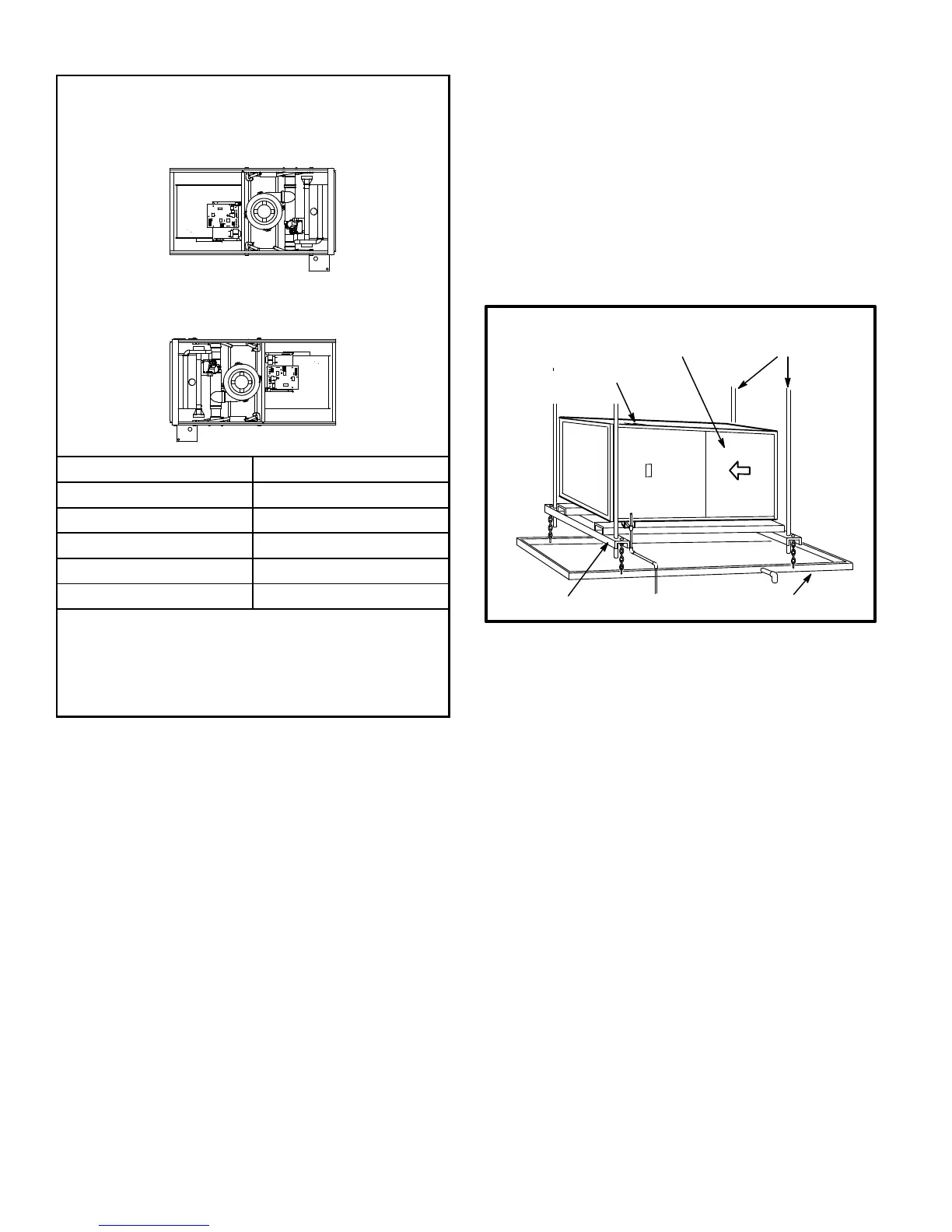
FIGURE 17
Suspended Installation of Horizontal Unit
NOTE − If unit is suspended in attic or crawl space, horizon-
tal support kit (Cat No. 56J18 ordered separately) must be
used to ensure proper unit support and coil drainage.
1 − Select location for unit keeping in mind service and
other necessary clearances. See figure 17.
2 − Provide service platform in front of unit.
3 − If unit is installed above finished space, fabricate a
drain pan fitted with a 1/2 inch or 3/4 inch N.P.T. fitting.
4 − Using 3/8 inch rods and support frame kit or field−fabri-
cated supports, fabricate suspension hangers, keep-
ing in mind front service access clearances.
5 − Mount unit on support frame as shown in figure 18.
6 − Continue with exhaust, condensate and intake line
piping instructions.
7 − If unit is suspended above finished space, hang the
field−provided drain pan below the support frame as
shown in figure 18. Leave 5−1/2 inches for service
clearance below unit for condensate trap.
8 − Route auxiliary drain line so that water draining from
this outlet will be easily noticed by the homeowner. If
necessary, run the condensate line into a condensate
pump to meet drain line slope requirements. The
pump must be rated for use with condensing furnaces.
Protect the condensate discharge line from the pump
to the outside to avoid freezing.
FIGURE 18
BLOWER ACCESS PANEL
3/8 in. RODS
SUPPORT FRAME
INTAKE/EXHAUST
CONNECTION
TYPICAL HORIZONTAL CEILING APPLICATION
DRAIN PAN
(to protect finished space)
Platform Installation of Horizontal Unit
1 − Select location for unit keeping in mind service and
other necessary clearances. See figure 17.
2 − Construct a raised wooden frame and cover frame
with a plywood sheet. Provide a service platform in
front of unit. If unit is installed above finished space,
fabricate a drain pan to be installed under unit.
When installing the unit in a crawl space, a proper sup-
port platform may be created using cement blocks and
the horizontal support frame kit (ordered separately,
Lennox part number 56J18). Position the support
frame on top of the blocks and install the unit on the
frame. Leave 5−1/2 inches for service clearance for
condensate trap.
3 − Route auxiliary drain line so that water draining from
this outlet will be easily noticed by the homeowner. If
necessary, run the condensate line into a condensate
pump to meet drain line slope requirements. The
pump must be rated for use with condensing furnaces.
Protect the condensate discharge line from the pump
to the outside to avoid freezing.
 Loading...


