Page 34
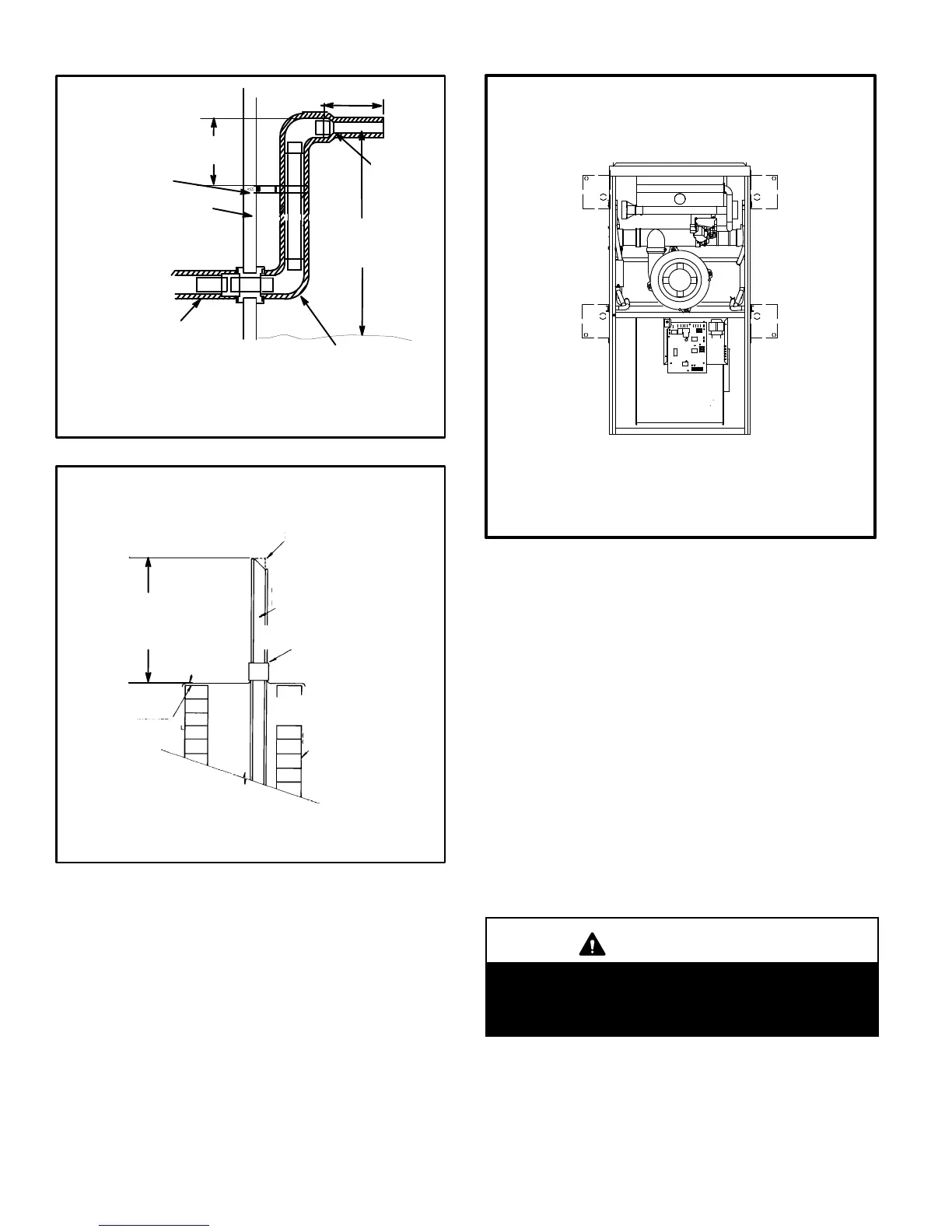
FIGURE 46
12" (305mm)
ABOVE GRADE OR
AVERAGE SNOW
ACCUMULATION
UNCONDITIONED
SPACE
1/2" (13mm) FOAM
INSULATION
1/2" (13mm) FOAM
INSULATION IN
UNCONDITIONED
SPACE
*WALL SUPPORT
OUTSIDE WALL
SIZE TER-
MINATION
PIPE PER
TABLE 8.
FIELD−PROVIDED
REDUCER MAY BE
REQUIRED TO
ADAPT LARGER
VENT PIPE SIZE TO
TERMINATION
*Use wall support every 24" (610). Use two supports if extension is
greater than 24" but less than 48".
12" (305mm) MAX. for 2" (51mm)
20" (508mm) MAX. for 3" (76mm)
NON−DIRECT VENT FIELD SUPPLIED WALL TERMINATION
EXTENDED OR (15F74) WALL TERMINATION VENT PIPE
EXTENDED
6" (152mm)
Max
NOTE − Do not discharge exhaust gases directly into any chimney or vent stack. If ver-
tical discharge through an existing unused chimney or stack is required, insert piping
inside chimney until the pipe open end is above top of chimney and terminate as illus-
trated. In any exterior portion of chimney, the exhaust vent must be insulated.
FIGURE 47
3" − 8"
(76mm−
203mm)
3" − 8"
(76mm−
203mm)
STRAIGHT−CUT OR
ANGLE−CUT IN DIRECTION
OF ROOF SLOPE
EXHAUST VENT
1/2" (13mm)
WEATHERPROOF
INSULATION
SHOULDER OF FITTINGS
PROVIDE SUPPORT
OF PIPE ON TOP PLATE
EXTERIOR
PORTION OF
CHIMNEY
INSULATE
TO FORM
SEAL
SHEET
METAL TOP
PLATE
SIZE TERMINATION
PIPE PER TABLE 8.
G61MPV NON−DIRECT VENT APPLICATION
USING EXISTING CHIMNEY
Minimum 12" (305MM)
above chimney top
plate or average snow
accumulation
Condensate Piping
This unit is designed for either right- or left-side exit of con-
densate piping in either upflow or downflow applications;
however, it must be installed on the same side of the unit as
the exhaust piping. In horizontal applications, the conden-
sate trap should extend below the unit. A 5−1/2" service
clearance is required for the condensate trap. Refer to fig-
ure 48 for condensate trap locations.
FIGURE 48
CONDENSATE TRAP LOCATIONS
(Unit shown in upflow position)
Horizontal
left and
optional
downflow
Horizontal
right and
optional
downflow
Optional
upflow
Optional
upflow
NOTE − In upflow applications where side return
air filter is installed on same side as the conden-
sate trap, filter rack must be installed beyond
condensate trap to avoid interference.
1 − Determine which side condensate piping will exit the
unit. Remove plugs from the condensate collar at the
appropriate location on the side of the unit.
NOTE − The condensate trap is factory−shipped with
two rubber O−rings and two rubber clean−out caps
installed. Check to make sure that these items are in
place before installing the trap assembly.
2 − Install condensate trap onto the condensate collar.
Use provided HI/LO screws to secure two upper
flanges of the trap to the collar. Use provided sheet
metal screw to secure bottom trap flange to side of
unit. DO NOT apply glue to secure condensate trap
to cabinet. All other joints must be glued. See figure
49.
NOTE − In upflow and downflow applications, con-
densate trap must be installed on the same side as
exhaust piping.
CAUTION
DO NOT use a power driver to tighten screws which
secure condensate trap to cabinet. Screws should
be hand−tightened using a screw driver to avoid the
possibility of damage to the trap assembly.

 Loading...


