Page 39
provided neutral terminals. See figure 56 for control
board configuration. This terminal is energized in the
heating mode when the combustion air inducer is oper-
ating.
9 − One 24V H" terminal is provided on the furnace control
board terminal block. Any humidifier rated up to 0.5
amp can be connected to this terminal with the ground
leg of the circuit being connected to either ground or
the C" terminal. See figure 56 for control board config-
uration.
10 −Install the room thermostat according to the instruc-
tions provided with the thermostat. See table 11 for
thermostat connections. If the furnace is being
matched with a heat pump, refer to the instruction
packaged with the dual fuel thermostat.
Indoor Blower Speeds
1 − When the thermostat is set to FAN ON," the indoor
blower will run continuously at approximately 38% of
the second−stage cooling speed when there is no cool-
ing or heating demand.
2 − When the G61MPV is running in the heating mode, the
indoor blower will run on the heating speed designated
by the positions of DIP switches 11 and 12.
3 − When there is a cooling demand, the indoor blower will
run on the cooling speed designated by the positions
of DIP switches 5 and 6.
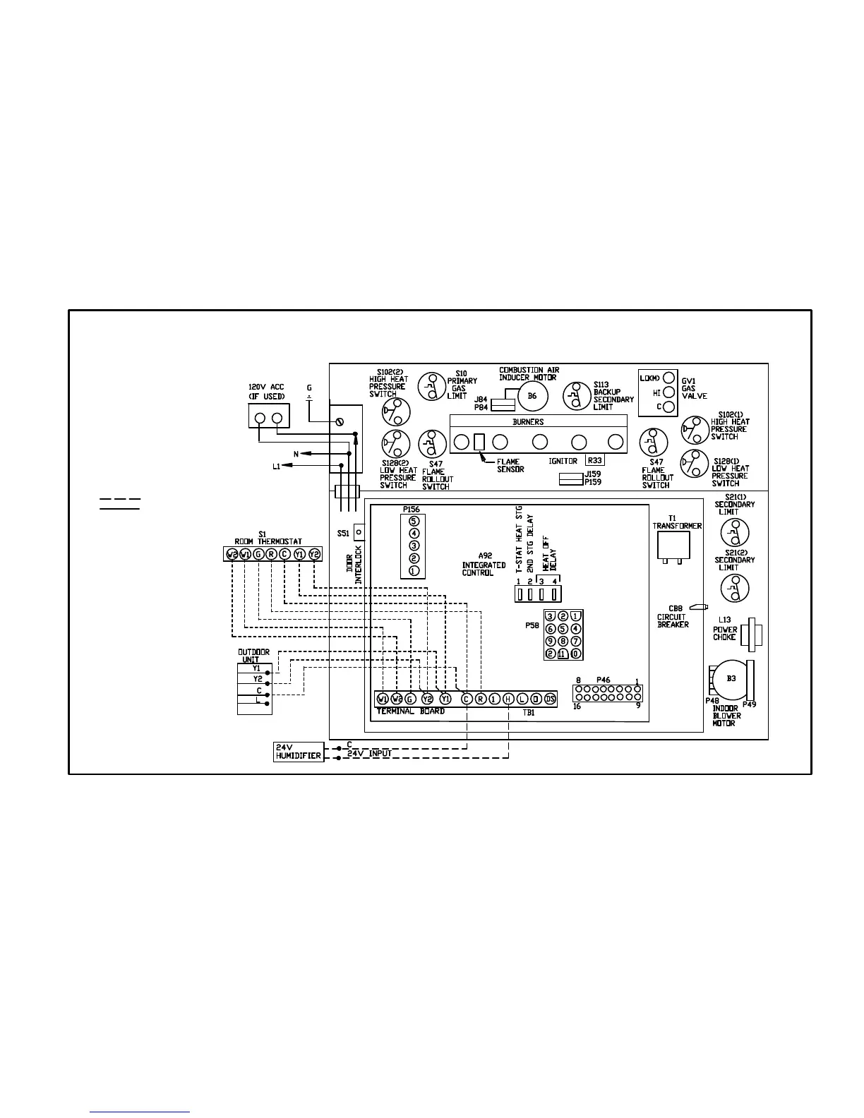
TYPICAL G61MPV FIELD WIRING DIAGRAM
FIGURE 55
FIELD INSTALLED CLASS II 24V
FIELD INSTALLED LINE VOLTAGE
USE COPPER CONDUCTORS ONLY.

 Loading...


