INTAKE
AIR
GRADE
//
//
//
//
iiiililili_!!iii!ii!ii!ii!ii!ii!ii!ii!ii!ii!i_!i!!i_i_ii_iiii_;_;!
12" (305) MAX. for 2" (51)
20" (508) MAX. for 3" (76)
(unless supported) Inches (ram)
f- 71- -- -Iq
(C_ 1 _ _ EXHAUST
i _-_- --J ..... IJ AIR
__11_[_/_ 8" (203) I
!1 II _ _ 12"(305)
)1 Minimum
ABOVEGRAOE
Side View
INTAKE
AIR
5"
(127
12"
COVER EXHAUST
VENT WITH
1/2" (13)
FOAM
INSULATION
EXHAUST
AIR
12" MIN.
(305)
Above Grade
GRADE
Front View
DIRECT VENT TERMINATION
WALL TERMINATION KIT (22G44, 44J40, 30G28 or 81J20) EXTENDED VENT FOR GRADE CLEARANCE
FIGURE 31
G71MPP DIRECT VENT APPLICATION
USING EXISTING CHIMNEY STRAIOHT-CUTOR
ANGLE-CUT IN DIRECTION
OF ROOF SLOPE *
8 12
(203mm 30_,m)
INTAKE P_PE
INSULATION (opfl_al)
SHEET
METALTOP
PLATE
MINIMUM 12"
(305ram) ABOVE
ROOF
*SIZE TERMINATION
PIPE PER TABLE 8.
EXHAUSTVENT
1_" (13ram)
WEATHERPROOF
INSULAT_N
SHOULDER OF FITQNGS
PROVIDE SUPPORT
OF PIPE ON TOP PLATE
i ALTERNATE
L--\:; ..,_._AKEP_PE
NOTE - Do not discharge exhaust gases directjy into any chimney or vent stack. If ver-
tical discharge through an existing unused chimney or stack is required, insert piping
inside chimney until the pipe open end is above top of chimney and terminate as illus-
trated. In any exterior portion of chimney, the exhaust vent must be insulated.
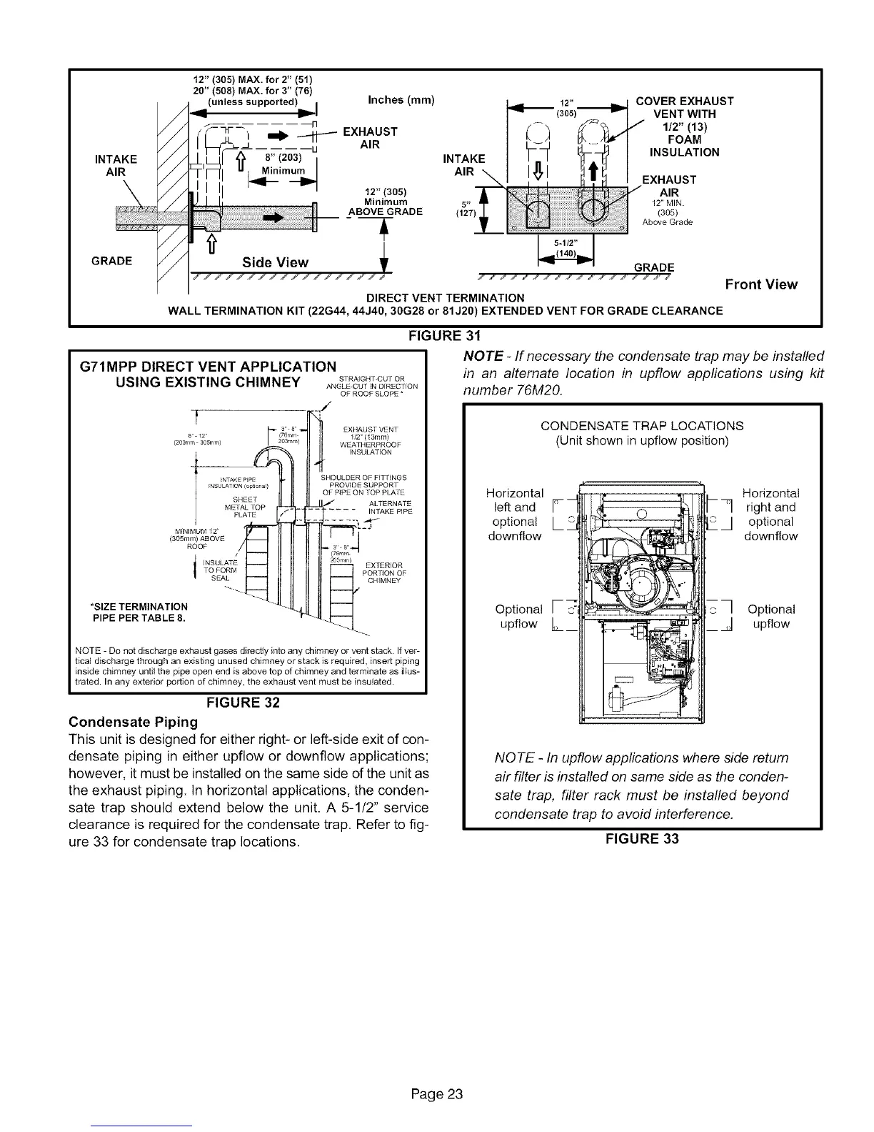
NOTE- If necessary the condensate trap may be installed
FIGURE 32
Condensate Piping
This unit is designed for either right- or left-side exit of con-
densate piping in either upfiow or downflow applications;
however, it must be installed on the same side of the unit as
the exhaust piping. In horizontal applications, the conden-
sate trap should extend below the unit. A 5-1/2" service
clearance is required for the condensate trap. Refer to fig-
ure 33 for condensate trap locations.
in an alternate location in upflow applications using kit
number 76M20.
CONDENSATE TRAP LOCATIONS
(Unit shown in upf!ow position)
Horizontal
left and
optional
downfiow
Optional
upflow
O
Horizontal
_] right and
J optional
downflow
Optional
upf!ow
NOTE - In upflow applications where side return
air filter is installed on same side as the conden-
sate trap, filter rack must be installed beyond
condensate trap to avoid interference.
FIGURE 33
Page 23
 Loading...