,-& WARNING
In addition to the requirements outlined previously, the fol-
lowing general recommendations must be considered
when installing a G71MPP furnace:
• Place the furnace as close to the center of the air dis-
tribution system as possible. The furnace should also be
located close to the chimney or vent termination point.
• When the furnace is installed in an attic or other insu-
lated space, keep insulation away from the furnace.
• When the furnace is installed in an unconditioned
space, consider provisions required to prevent freezing
of condensate drain system.
I
-&WARNING
I
,&,CAUTION
These instructions are intended as a general guide and do
not supersede local codes in any way. Consult authorities
having jurisdiction before installation.
UPFLOW APPLICATION
O
t1"
AIR FLOW
FRONT VIEW
UNIT
FRONT
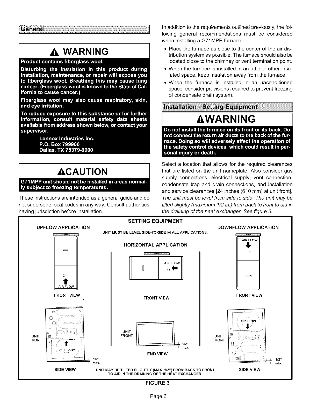
Select a location that allows for the required clearances
that are listed on the unit nameplate. Also consider gas
supply connections, electrical supply, vent connection,
condensate trap and drain connections, and installation
and service clearances [24 inches (610 mm) at unit front].
The unit must be level from side to side. The unit may be
tilted slightly (maximum 1/2 in.) from back to front to aid in
the draining of the heat exchanger. See figure 3.
SETTING EQUIPMENT
UNIT MUST BE LEVEL SIDE-TO-SIDE IN ALL APPLICATIONS.
HORIZONTAL APPLICATION
SIDE VIEW
UNIT
FRONT
112"
max.
FRONT VIEW
1/2"
I rflax,
UNIT
FRONT
EN D VIEW
UNIT MAY BE TILTED SLIGHTLY (MAX. 1/2") FROM BACK TO FRONT
TO AID IN THE DRAINING OF THE HEAT EXCHANGER.
DOWNFLOW APPLICATION
AIR FLOW
!,
m
FRONT VIEW
©
1/2"
rflax.
SIDE VIEW
FIGURE 3
Page 6
 Loading...