Page 20
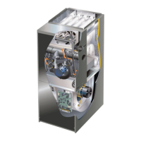
FIGURE 21
TYPICAL AIR INTAKE PIPE CONNECTIONS
UPFLOW OR DOWNFLOW DIRECT VENT APPLICATIONS
(Right−Hand Exit in Upflow Application Shown)
PLUG
(Must be
glued in
place)
*Limit pipe length to 4" in
G71MPP−135 applications.
−36B−070
−36C−090
−60C−090
−36B−070
−36C−090
−60C−090
−60C−110
−36B−070
−36C−090
−60C−090
−60C−110
−60D−135*
2
2
2
2
2
2
2−1/2",
3" OR
4
TRANSITION
2"*
TRANSITION
2−1/2",
3" OR
4
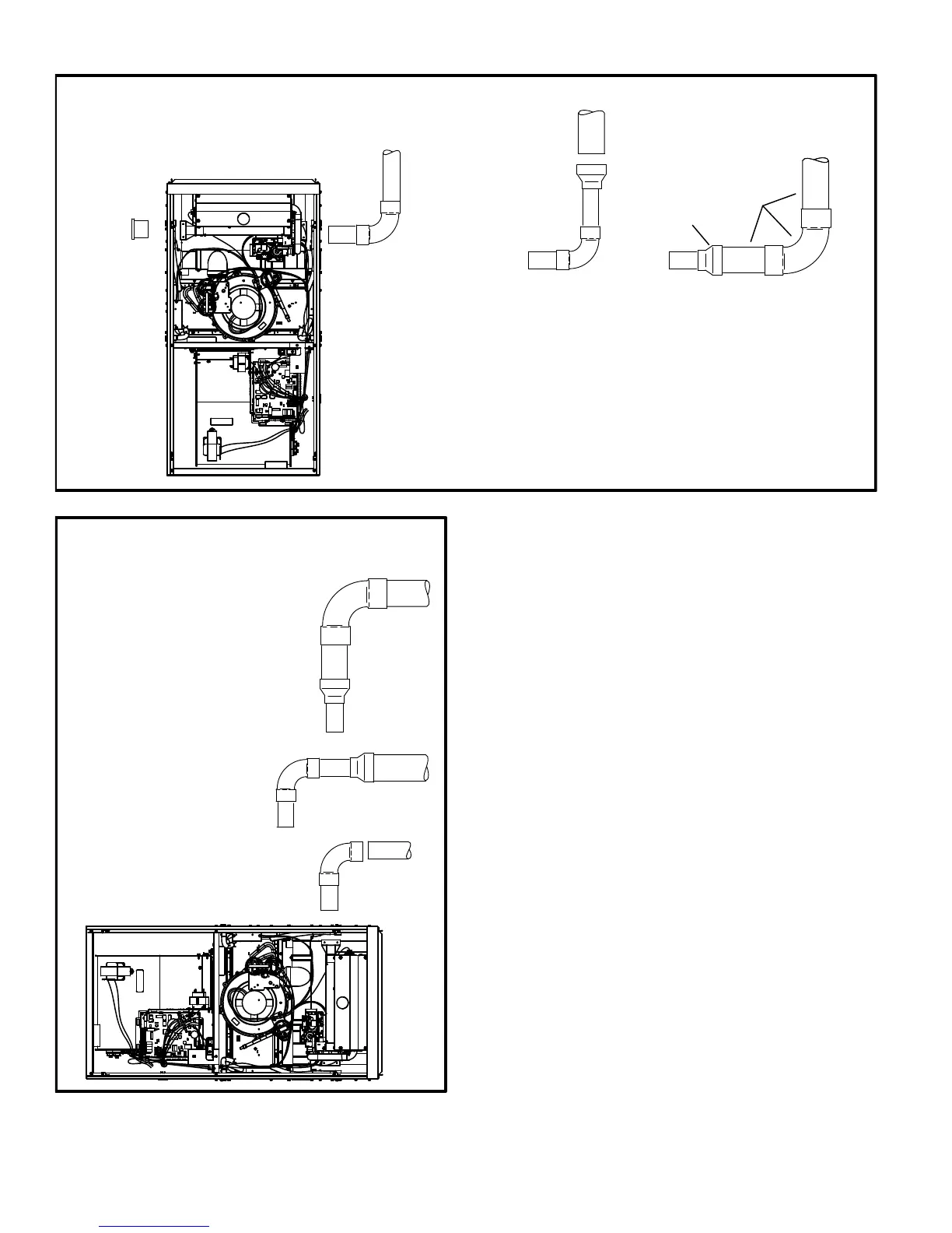
FIGURE 22
TYPICAL AIR INTAKE PIPE CONNECTIONS
HORIZONTAL DIRECT VENT APPLICATIONS
(Horizontal Right−Hand Air Discharge Application Shown)
2”*
2”
2”
2”
TRANSITION
TRANSITION
2”
2−1/2”,
3” OR 4”
2−1/2”,
3” OR 4”
*Limit pipe
length to 4" in
−135 applications.
2”
−36B−070
−36C−090
−60C−090
−60C−110
−60D−135*
−36B−070
−36C−090
−60C−090
−60C−110
−36B−070
−36C−090
−60C−090
2”
 Loading...