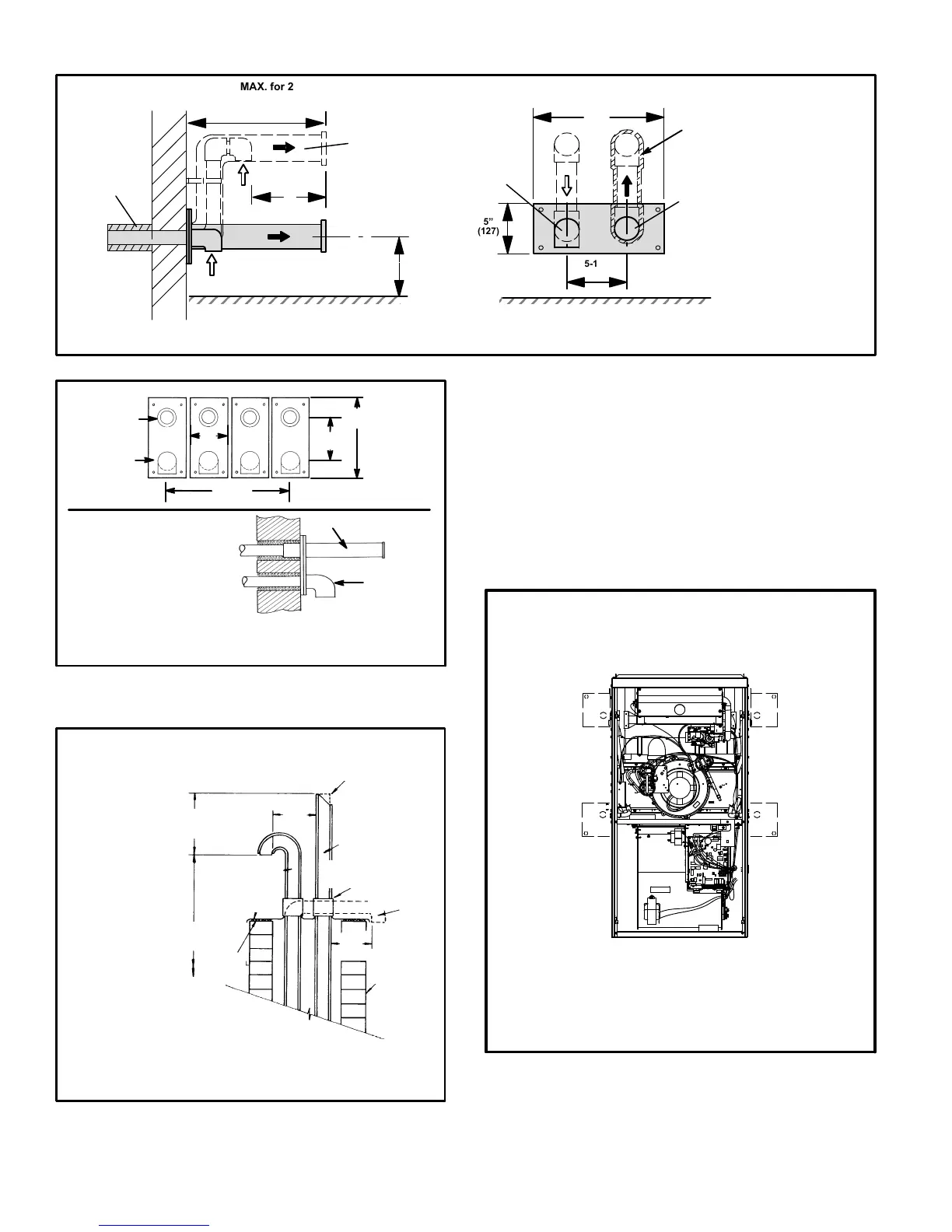
12" (305) MAX. for 2" (51)
20" (508) MAX. for 3" (76)
(unless supported)
Minimum 12"
(305)
above grade or
average snow
accumulation.
Minimum 12"
(305)
above grade or
average snow
accumulation.
INTAKE
VENT
(with optional
elbow)
FIGURE 31
EXHAUST
VENT
Front View
12"
(305)
5"
(127)
18" MAX.
(457)
EXHAUST VENT
INTAKE
VENT
(with optional
elbow)
OPTIONAL VENT TERMINATION FOR MULTIPLE UNIT
INSTALLATION OF DIRECT VENT WALL TERMINATION KIT (30G28)
Inches (mm)
Side View
5−1/2"
(140)
G71MPP DIRECT VENT APPLICATION
USING EXISTING CHIMNEY
NOTE − Do not discharge exhaust gases directly into any chimney or vent stack. If ver-
tical discharge through an existing unused chimney or stack is required, insert piping
inside chimney until the pipe open end is above top of chimney and terminate as illus-
trated. In any exterior portion of chimney, the exhaust vent must be insulated.
FIGURE 32
8" − 12"
(203mm − 305mm)
3" − 8"
(76mm−
203mm)
3" − 8"
(76mm−
203mm)
STRAIGHT−CUT OR
ANGLE−CUT IN DIRECTION
OF ROOF SLOPE *
EXHAUST VENT
1/2" (13mm)
WEATHERPROOF
INSULATION
SHOULDER OF FITTINGS
PROVIDE SUPPORT
OF PIPE ON TOP PLATE
ALTERNATE
INTAKE PIPE
INTAKE PIPE
INSULATION (optional)
EXTERIOR
PORTION OF
CHIMNEY
INSULATE
TO FORM
SEAL
SHEET
METAL TOP
PLATE
*SIZE TERMINATION
PIPE PER TABLE 8.
Minimum 12" (305)
above roof or average
snow accumulation.
Condensate Piping
This unit is designed for either right- or left-side exit of con-
densate piping in either upflow or downflow applications;
however, it must be installed on the same side of the unit as
the exhaust piping. In horizontal applications, the conden-
sate trap should extend below the unit. A 5−1/2" service
clearance is required for the condensate trap. Refer to fig-
ure 33 for condensate trap locations.
NOTE − If necessary the condensate trap may be installed
in an alternate location in upflow applications using kit num-
ber 76M20.
FIGURE 33
CONDENSATE TRAP LOCATIONS
(Unit shown in upflow position)
Horizontal
left and
optional
downflow
Horizontal
right and
optional
downflow
Optional
upflow
Optional
upflow
NOTE − In upflow applications where side return
air filter is installed on same side as the conden-
sate trap, filter rack must be installed beyond
condensate trap to avoid interference.
1 − Determine which side condensate piping will exit the
unit. Remove plugs from the condensate collar at the
appropriate location on the side of the unit.
 Loading...