LIFTING BRACKETS (4)
TWO EACH SIDE
FIGURE 9
LIFTING BRACKETS
SIDE VIEW
Page 22
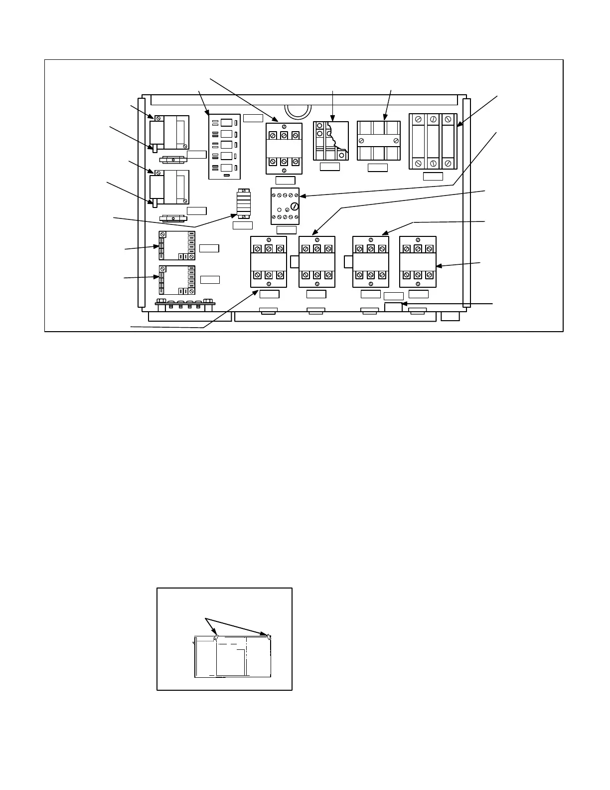
FIGURE 8
GCS16-2553, 2753, 3003 UNIT CONTROL BOX
F10
TB13
K3
S42
F16
K10K68 K2 K1
S3
A9
A10
T1
T18
A11
TB17
PILOT RELAY BOARD A11
INDOOR BLOWER CONTACTOR K3
CONTACTOR
TRANSFORMER
T18
CONTROL
TRANSFORMER T1
TERMINAL
STRIP TB17
COMPRESSOR
PROTECTOR A9
COMPRESSOR
PROTECTOR A10
POWER DISTRIBUTION
BLOCK TB13
OUTDOOR FAN
MOTOR FUSE F10
INDOOR BLOWER
MOTOR FUSE F16
INDOOR BLOWER
MOTOR
OVERLOAD
RELAY S42
2nd STAGE
CONDENSER FAN
CONTACTOR K68
2nd STAGE
COMPRESSOR
CONTACTOR K2
1st STAGE
COMPRESSOR
CONTACTOR K1
1st STAGE
CONDENSER
FAN CONTACTOR
K10
COMPRESSOR
MONITOR/
LOW TEMP LIMIT
S3
FUSE F1
FUSE F18
I-APPLICATION
Refer to the Engineering Handbook for specific application
data. All units are factory equipped with the hardware required
for installation of Lennox' optional thermostat control systems.
Lennox' control systems are the same controls, harnesses,
and harness plugs used in all 11, 15 and 16 series commer
cial units (except for early 11 series units which were
equipped with integral control system). For example, a
Honeywell W973 control will plug in to a GCS16-1853 as eas
ily as it will plug in to a GCS16-411 (and no field wiring is re
quired for either).
II-UNIT COMPONENTS
An overview of GCS16 components is shown in figures 1, 2,
3 and 4.
A-Lifting Brackets
Each unit is equipped
with factory installed lift
ing brackets as shown in
figure 9. Brackets are
used for lifting the unit
during installation or
when servicing. Lifting
lugs can be removed
from the unit and reused.
If unit must be lifted for service, use only lifting brackets to
lift unit.
B-Control Box Components
GCS16 control box is shown in figures 5, 6, 7 and 8. The con
trol box is located in the upper portion of the compressor
compartment behind the compressor compartment access
panel. In larger units, a hinged door with magnetic latch lo
cated behind the compressor access panel, provides access
to control components.
1-Power Distribution Terminal Block TB13
(1853, 2553, 2753, 3003)
Larger GCS16 units use a power distribution terminal
block to provide a line voltage electrical connection be
tween the control box components and the power entry
area in the heating compartment. Line voltage cables con
nect TB13 with the unit terminal block TB2 located in the
heating compartment.
2-Terminal Strip TB1
All GCS16 commercial units are equipped with a low voltage
terminal strip (TB1). The strip is used for making up all indoor
thermostat and outdoor unit low voltage control wiring con
nections (see figures 10 and 38). In 10 ton and smaller units,
TB1 is located in the unit control box. In 12.5 ton and larger
units, the terminal strip is located in the blower compartment.
A separate access panel is provided adjacent to the blower
access panel.
TB1 uses spring crimp type retainers for securing wires. A
small slot screwdriver must be used to depress the spring
in order to insert or remove a wire (see figure 10). Strip
wire no more than 1/4".
 Loading...
