Page 16
FIGURE 9
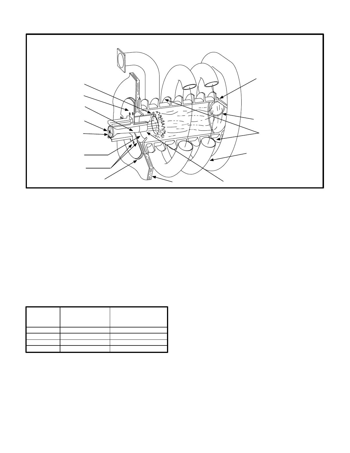
GCS16 HEAT EXCHANGE ASSEMBLY
ORIFICE
BURNER PLATE
HELICAL ALUMINIZED
STEEL TUBE
EXHAUST
(SECONDARY)
CAST IRON
CYLINDRICAL
HEAT EXCHANGER
(PRIMARY)
BURNER CONE
GASKET
BURNER
HEAT FINS
EXHAUST PORT
NON-ADJUSTABLE
ENDCAP
AIR OPENINGS
INSULATION
FLAME SPREADER
-50, -75, ONLY
RETENTION RING
1-Heat Exchanger (Figure 9)
All units use a cast iron cylindrical heat exchanger (prima
ry) encircled by helical aluminized steel tube exhaust (sec
ondary). Heat is transferred to the airstream from all sur
faces of the primary and secondary. A single inshot burner
is directed at a spreader in the heat exchanger and a com
bustion air blower is used to pull combustion air through
the heat exchanger. Heat exchangers are configured as
shown in Table 1.
TABLE 1
Btuh
Heat Exchanger
(Primary)
Size
Heat Exchanger
(Secondary)
No. of Wraps Around
Primary
50,000
75,000
100,000
125,000
Small
Large
2
3
4
5
Small
Large
2-Burner Assembly (Figures 10 and 11)
The burner is controlled by the spark electrode, flame
sensing electrode, gas valve GV1 and combustion air
blower B6. The spark electrode, flame sensing electrode
and gas valve GV1 are directly controlled by ignition con
trol A3. Ignition control A3 is controlled by combustion air
blower B6. Combustion air blower B6 is controlled by heat
ing demand from the thermostat or control system.
The burner is factory set and does not require adjustment.
Burner end caps (if used - see figure 9 ) are non-adjust
able. Flame can be viewed through air holes in the burner
plate. A peep hole is provided in the burner access panel
on units without a burner enclosure. If a burner enclosure
is used, a flame viewing glass is provided in the enclosure.
Combustion takes place at the heat exchanger entrance.
Combustion air is pulled through the burner by the com
bustion air blower (B6). Air is mixed with fuel in the burner.
The mixture is then ignited by the spark electrode and the
resultant flame is directed against a flame spreader. The
spreader disrupts and spreads the flame. The burner cone
surrounding the entrance to the heat exchanger directs
additional combustion air into the flame. A flame retention
ring located in the burner end is used to keep flame from
lifting off the burner head. As hot exhaust gases are drawn
through the heat exchanger by the combustion air blower,
exhaust gases are expelled from the heat exchanger sec
ondary and fresh air/gas mixture is drawn in through the
burner and supply air holes. Supply air blower B3, con
trolled by blower relay K25 forces air across all surfaces of
the heat exchanger primary and secondary to extract the
heat of combustion.
 Loading...