Page 17
a-Burners
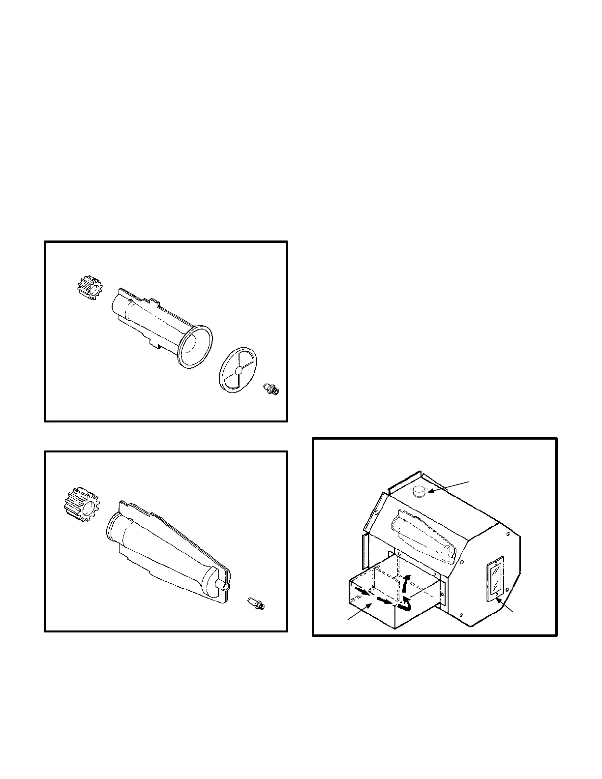
All units use an inshot burner (see figures 10 and 11). A
flame retention ring located in the burner end is used to
keep flame from lifting off the burner. The flame is aimed at
a round flame spreader located in the combustion cham
ber. The spreader distributes the flame evenly around the
circumference of the heat exchanger. Burners in 50,000
and 75,000 Btuh heat exchangers use a separate nonad
justable endcap (see figure 10). Burners in 100,000 and
125,00 Btuh heat exchangers do not use an endcap (see
figure 11).
INSHOT BURNER
50,000 and 75,000 Btuh HEAT EXCHANG
ERS
FIGURE 10
FLAME
RETENTION
RING
BURNER
SEPARATE
NON-ADJUSTABLE
ENDCAP
ORIFICE
INSHOT BURNER
100,000 and 125,000 Btuh HEAT EXCHANG
ERS
FIGURE 11
FLAME
RETENTION
RING
BURNER
ORIFICE
b-Orifice
All GCS16 units use an orifice which is precisely matched
to the burner input. The burner is supported by the orifice
and will easily slide off for service.
Each orifice and burner are sized specifically to the unit.
Refer to Lennox Repair Parts Listing for correct sizing in
formation.
3-Burner Enclosure
The following units are equipped with a burner enclosure
surrounding the burner assembly:
GCS16R-510-125, GCS16-510-125,
GCS16R-650-125, GCS16-650-125,
GCS16R-411-100, & GCS16H-311-75.
The enclosure is used to reduce sound levels in the burner
area. The enclosure consists of a metal wrapper sur
rounding the burner assembly and a glass flame viewing
window (see figure 12).
The burner can be inspected and the spark/sensor elec
trode removed by removing the burner enclosure sight
glass plate. If the burner must be removed or the orifice
accessed, the burner enclosure must be removed. Burner
enclosure and burner removal is detailed in the mainte
nance section of this manual.
Units equipped with burner enclosure are also equipped
with flame rollout switch. The switch provides unit protec
tion by shutting down the unit when flame rollout is sensed.
FIGURE 12
GCS16/GCS16R/GCS16H
BURNER ENCLOSURE
FLAME
ROLLOUT
SWITCH
SIGHT
GLASS
AIR INTAKE
 Loading...