Page 18
4-Blower / Limit Control:
High Temperature Limit S10,
Blower Control K25
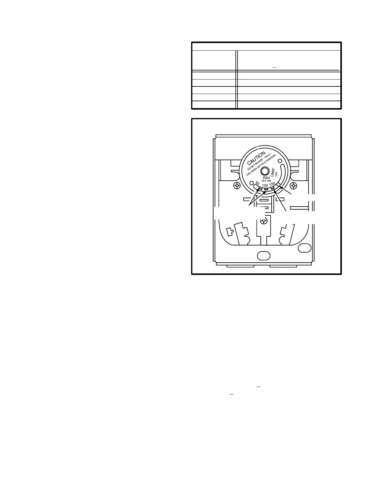
A combination blower/limit control with a bimetal sure
start heater (figure 13) is used to control blower operation
and protect unit from high temperature operation. It is lo
cated in the upper end of the heating vest panel. The blow
er control heater is a resistive type bemetal heat relay
(K25) used to reduce the time between blower demand
and blower startup. It is energized with the heating de
mand.
Internal contacts K25 are used to coordinate blower op
eration with burner operation. The N.O. contacts are actu
ated by a bimetal spring when temperature rise in the heat
ing compartment (in addition to heat added by the sure
start heater) is sufficient. The blower cycles on 20 to 90
seconds after the start of a heating demand and cycles off
120 to 240 seconds after heat demand is satisfied (when
bimetal swtich cools). Ontime will vary, depending on the
voltage applied to the bimetal heater and on the tempera
ture surrounding the K25 switch. The relay is SPST.
The blower control has a factory off setting of 90F. This
control can be field adjusted. In some cases, an unusual
duct design can cause the indoor blower to cycle on after
the heat demand is satisfied. If this situation occurs, the
Fan Off" setting on the blower/limit control should be set
below 90F. See figure 13.
NOTE - Blower OFF" settings above 90F will cause
the blower to recycle frequently (after a heating cycle)
due to residual heat in the heat exchange assembly.
Blower OFF" settings above 90F may also cause
nuisance trips of secondary limit S10.
Adjustment procedure is outlined in Heating System Ser
vice Checks" section.
Primary limit S10 contacts deenergize the ignition control
when excessive temperature is reached in the blower
compartment. The N.C. limit is a SPST autoreset switch.
It is fixed in position for a maximum discharge air tempera
ture. The limit is factory preset to trip on a temperature rise
and automatically reset on a temperature fall. On a tem
perature rise terminals 1-3 open to deenergize the igni
tion circuit. Table 2 shows factory settings. This is a safety
shutdown function of the unit.
TABLE 2
LIMIT CONTROL S10
Unit Input
Thousand
Btuh
High Limit
Cutout
+ 10F
50
75
100
510-125
160F
170F
150F
170F
650-125 160F
FIGURE 13
HONEYWELL BLOWER/LIMIT CONTROL
BLOWER SETTING
POINTERS
LIMIT SETTING
POINTER
FIXED STOP
5-Secondary Limit S21
100,000 Btuh Heat Exchangers Only
All GCS16-410-100 and GCS16R-411-100 units are
equipped with a secondary high temperature limit located
on the blower scroll (see figure 14). The limit is a SPST
autoreset temperature which opens (terminals 1-3) on a
temeprature rise. It is electrically connected in series with
the ignition control. The limit is used to deenergize the
ignition control and shut down the unit when temperature
in the blower scroll becomes too high. The limit is factory
preset to open at 170F+5F on a temperature rise and
close at 130F+10F on a temperature fall. It is not adjust
able. This is a safety shutdown function of the unit.
 Loading...