Page 55
3- If a thermostat demand is present at the end of the 3-7
minute timed off period, the compressor is immediate
ly energized.
4- If there is no thermostat demand at the end of the 3-7
minute timed off period, the compressor remains de
energized until the next thermostat demand when all
safety circuits are closed.
Wiring:
1- Disconnect power to the unit.
2-Make wiring connections per wiring diagram in
figure 68.
L-OptionalCompressorMonitor(Figure69)
Y1
W1
G
4
5
6
7
8
9
10/R
11
Y2
W2
14
15
TB1
TERMINAL
STRIP*
LOSS OF CHARGE
SWITCH*
HIGH PRESSURE
SWITCH*
GCS16 UNIT CONTROL BOX
FIELD WIRING COMPRESSOR MONITOR
ALL MODELS
24VAC FIELD INSTALLED
24VAC FACTORY INSTALLED
J3-2
FIGURE 69
*Not furnished on all units.
TO COMPRESSOR
CONTACTOR COIL
DEMAND FROM
THERMOSTAT
TERMINAL Y
*
Optional compressor monitor can be installed in all units
to provide low ambient protection for the compressor. The
monitor (figure 69) is a N.O. temperature switch located in
the control box area. It is wired in series with the compres
sor contactor. When ambient temperature drops below
40F, the switch opens and deenergizes the circuit to the
compressor contactor thereby protecting the compressor
from low ambient operation.
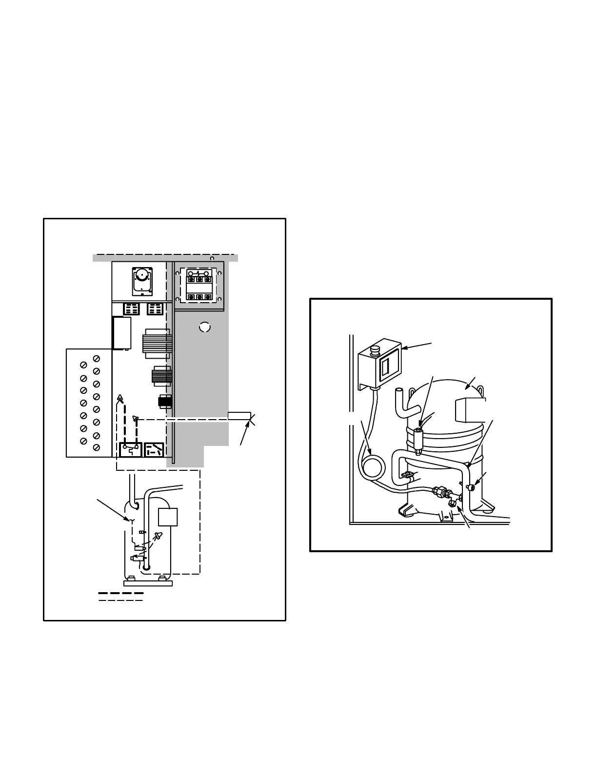
M-Low Ambient Kit
The optional low ambient kit (figure 70) allows for mechan
ical cooling operation at low outdoor temperature.
CAUTION - Compressor monitor cannot be used with
optional low ambient kit. Optional field installed com
pressor monitor MUST be disconnected before allow
ing low ambient kit to be used.
FIGURE 70
TYPICAL INSTALLATION
LOW AMBIENT
PRESSURE SWTICH
HIGH PRESSURE
SWITCH
COMPRESSOR
DISCHARGE
LINE
LOSS OF
CHARGE
SWITCH
VALVE
DEPRESSOR TEE
SHOCK
LOOP
LOW AMBIENT KIT
Low ambient kit field wiring is shown in figure 71. The low
ambient pressure switch is wired in series with the con
denser fan L1 lead. Refer to the low ambient kit installation
instruction manual for detailed installation instructions.
 Loading...