Page 52
FIGURE 57
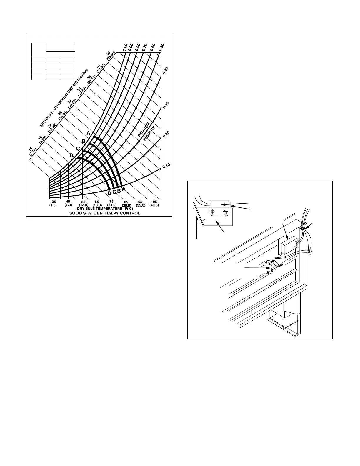
ENTHALPY CHART
CHART
CURVE
CONTROL
POINT 50% RH
°F °C
A
B
C
D
73
70
67
63
23
21
19
17
Two types of adjustment may be made at the control.
The first is the control setpoint. The setpoint deter
mines the temperature and humidity conditions at
which the outdoor air dampers will open and close.
The recommended setpoint is A." If the economizer
is allowing air which is too warm or too humid into the
system, the control may be changed to a lower set
point (B,C or D). Refer to enthalpy chart figure 57.
Example:
If the enthalpy control is set at setpoint A" as shown in
figure 57, the following situation could occur. A cooling
demand when the outside air is at 75° and 20 percent
humidity would drive the economizer outdoor air
dampers open to utilize outdoor air for cooling. The
compressor cooling circuit would be disabled. Howev
er, if the outdoor air should change to 70°F (a drop in
temperature) and 70 percent humidity (a dramatic rise
in humidity), the total heat content" of the outdoor air
would rise above the enthalpy control setpoint and de-
activate the damper motor to the preset minimum posi
tion. If cooling demand is still present when the total
heat of the outside air rises above the control setpoint,
cooling demand is routed from the economizer to the
compressor cooling circuit.
b-Minimum Positioner
The second type of adjustment which may be made
at the control is the minimum position of the outdoor
damper blades. Each economizer has a minimum
positioner switch (potentiometer) which allows the
outdoor dampers to be adjusted to a preset minimum
position. This allows a preset amount of air exchange
at all times during blower operation. When unit opera
tion stops, the dampers drive closed. The potentiom
eter is located on the enthalpy control face.
c-Enthalpy Sensor
The enthalpy sensor is located on the outside portion
of the outdoor damper blades (as shown in figure 58).
The sensor monitors the total heat content of the out
door air (temperature plus humidity) and sends the in
formation to the enthalpy control. The enthalpy control
uses the information to determine if outdoor air can be
used for cooling.
FIGURE 58
MERCURY
SWITCH
(optional PED16 only)
ENTHALPY
SENSOR
WIRE
TIE
BRACKET
DAMPER BLADE
MERCURY SWITCH
SWITCH STRAP
REMD16M-185,-300
ENTHALPY SENSOR AND MERCURY SWITCH
d-Mixed Air Sensor
The mixed air sensor measures the resultant tempera
ture of the mixed air downstream from the evaporator
coil. Temperature is measured in the heating compart
ment (figure 59). The mixed air temperature is used by
the enthalpy control when outdoor dampers are open to
help determine outdoor air damper position. The econ
omizer is factory equipped with a single mixed air sen
sor which fits through a factory supplied hole in the pan
el dividing unit return and supply air (see figure 59).
 Loading...
