Page 57
1-SP11 Application
The SP11 may be applied to any control system. To
operate an SP11, a readout relay kit including an elec
tric heat current sensing relay is required to interface
the ECH16 to the SP11. Optional filter switch kit must
be added in order to make the filter light functional.
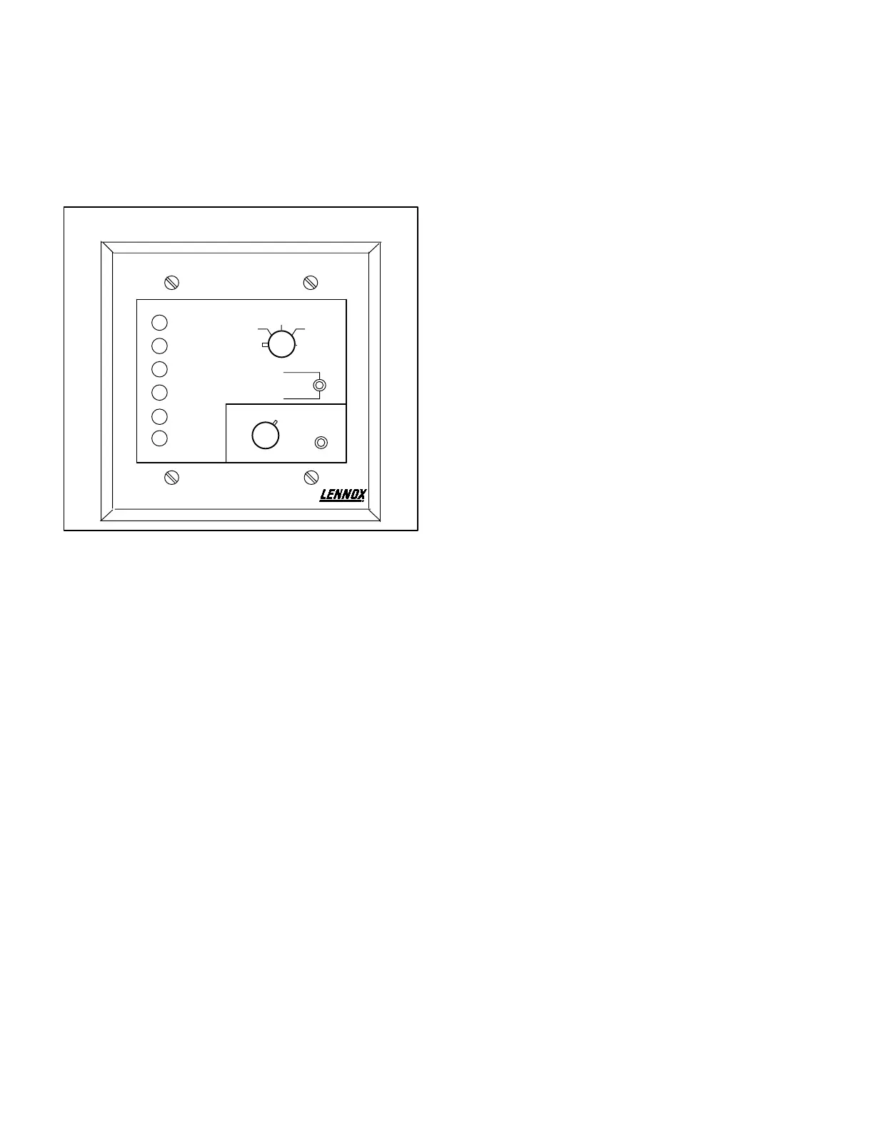
FIGURE 67
SSP11 SWITCHING STATUS PANEL
Cool Mode
Heat Mode
Compressor 1
Compressor 2
No Heat
Filter
OFF
HEAT
AUTO
COOL
EM HEAT
AFTER HOURS TIMER
START
SYSTEM
FAN
AUTO
ON
2-SSP11 Application
The SSP11 may be applied to units using standard
electromechanical thermostat or Honeywell W973
control systems only. The W7400 and T7300 control
systems provide switching features similar to the
SSP11, therefore, the SSP11 is not needed. To oper
ate an SSP11, a readout relay kit is required to inter
face the to the SSP11. An SSP11 relay kit is also re
quired (in addition to the readout relay kit and current
sensing relay) in units using an electromechanical
thermostat.
Optional filter switch kit is required to make the
dirtyfilter light functional.
3-Indications and Functions
Both status panels are identical in function except for
the switching and after hours capabilities of the
SSP11.
a- The COOL MODE" LED lights green to indicate
economizer free cooling" operation when unit in
cludes the economizer option. Otherwise the LED
indicates mechanical cooling operation.
b- The HEAT MODE" LED lights green during normal
heating operation.
c- The COMPRESSOR 1" LED lights green when
compressor 1 is running. The light turns red if a
compressor safety switch opens during a compres
sor demand.
d- The COMPRESSOR 2" LED lights green when
compressor 3 is running. The light turns red if a
compressor safety switch opens during a compres
sor demand.
e- The NO HEAT" LED lights red on a loss of heat dur
ing a heating demand.
f- The FILTER" LED lights red when optional pressure
switch contacts close indicating dirty filters.
g- The SYSTEM" switch on the SSP11 has five posi
tions to indicate the following functions:
OFF" - System off.
HEAT" - System operates in heating mode only.
AUTO" - System automatically provides heating or
cooling on demand.
COOL" - System operates in cooling mode only.
EM HEAT" - (Emergency Heat) Not used in units,
but if placed in this position, the unit operates in the
normal heating only mode.
h- The FAN" switch on the SSP11 has two positions to
indicate the following functions:
AUTO" - Blower cycles with demand.
ON" - Blower runs continuously.
i- The AFTER HOURS TIMER" on the SSP11 pro
vides override of unoccupied mode operation (night
heating setback / cooling setup) from 0 to 12 hours.
In the occupied (day) mode, the after hours timer
has no effect on unit operation.
The unit must be in the unoccupied mode (night) to
activate the timer. Set the potentiometer for the
number of hours desired override and push the mo
mentary start button. The unit reverts to occupied
mode operation for the set number of hours.
 Loading...
