Page 59
10- Jack J57 / (opt. Plug P57)
(used in 15 ton and larger units only)
Jack J57 is located in the unit control box. It is wired to
the unit wiring harness and to jack J25 and is used for
the connection of an optional dirty filter" indicator
switch to the optional status panel.
The matching plug P57 is located in dirty filter"
switch assembly. Note that this switch assembly
does not perform any function unless the optional
status panel is installed.
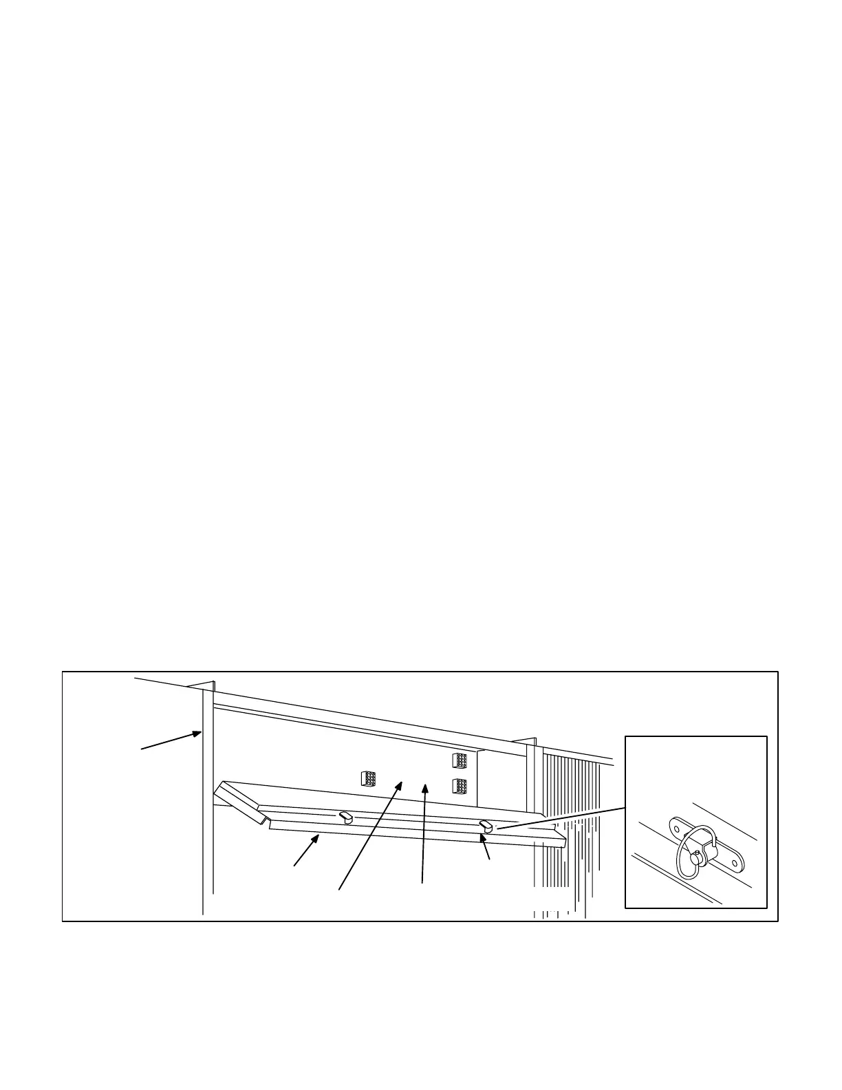
In 12.5 ton and smaller units, access to the unit filter section
is gained by removing the filter access panel. In 15 ton and
larger, an access door is provided. Access to the unit filter
section is gained by loosening the two quarter-turn fasteners
on the access door (figure 68) with a slot screwdriver. The
quarter-turn fasteners hold the access door shut with a spiral
spring. Once the fasteners are loosened, the filter access
door hinges open.
K-Optional Commercial Controls Systems
Optional 16 Series Commercial Controls" may be con
nected to any GCS16 series commercial unit. These are
the same controls which are optional in all 16 series com
mercial units. The following list describes the components
used in all currently available (at time of printing) optional
control system combinations. Each system is assigned a
C" number for easy reference. The C" number identifies
the control system on the wiring diagram (likewise, each
GCS16 unit wiring diagram is assigned a B" number, each
heating section is assigned an A" number and each econo
mizer diagram is assigned a D" number). Look for these
numbers on the diagram to help you identify how the unit is
setup and the control system being used.
The control system wiring diagrams and the accompany
ing system Operation Sequences" are not included in this
manual. Look for the control system diagrams and the op
eration sequence sections in the 16 Series Control Sys
tems" manuals printed separately.
The following section is provided to help service personnel
become familiar with Lennox' Commercial Controls and
the associated wiring schemes.
1- D5 Wiring Diagram - Modulating Economizer
Model Number REMD16M-185
Downflow Modulating Economizer. Optional field
installed in all GCS16 units. Sensors continuously
monitor air conditions and adjust dampers according
ly. Infinite number of damper positions.
All wiring connections are made by jackplug connec
tions to the commercial controls harness in the unit.
Plug P4 in the economizer connects to Jack J3 in the
unit to make this connection.
2- Warm-Up Kit
Warm-up kit is shown in Figure 69. Warm-up kit is an
accessory to the economizer (diagram D5). The kit
provides warm-up capabilities by holding outdoor air
dampers closed during the first heating period after
night setback. When first heating demand is satisfied,
warm-up kit allows outdoor air dampers to open to
minimum position.
Warm-up kit does not have its own wiring diagram. It
is included in the C2, C4, C6 and C14 wiring dia
grams.
FIGURE 68
TYPICAL FILTER ACCESS SECTION 15 TON AND LARGER
UNITS
J24
J3
J33
UNIT FILTER
SECTION
ACCESS DOOR
1/4 TURN LATCH
ECONOMIZER ENTHALPY
CONTROL INSTALLS IN THIS AREA
PED16 CONTROL
INSTALLS IN THIS AREA
CONDENSER
FILTER ACCESS DOOR
QUARTER-TURN
FASTENER
 Loading...
