46
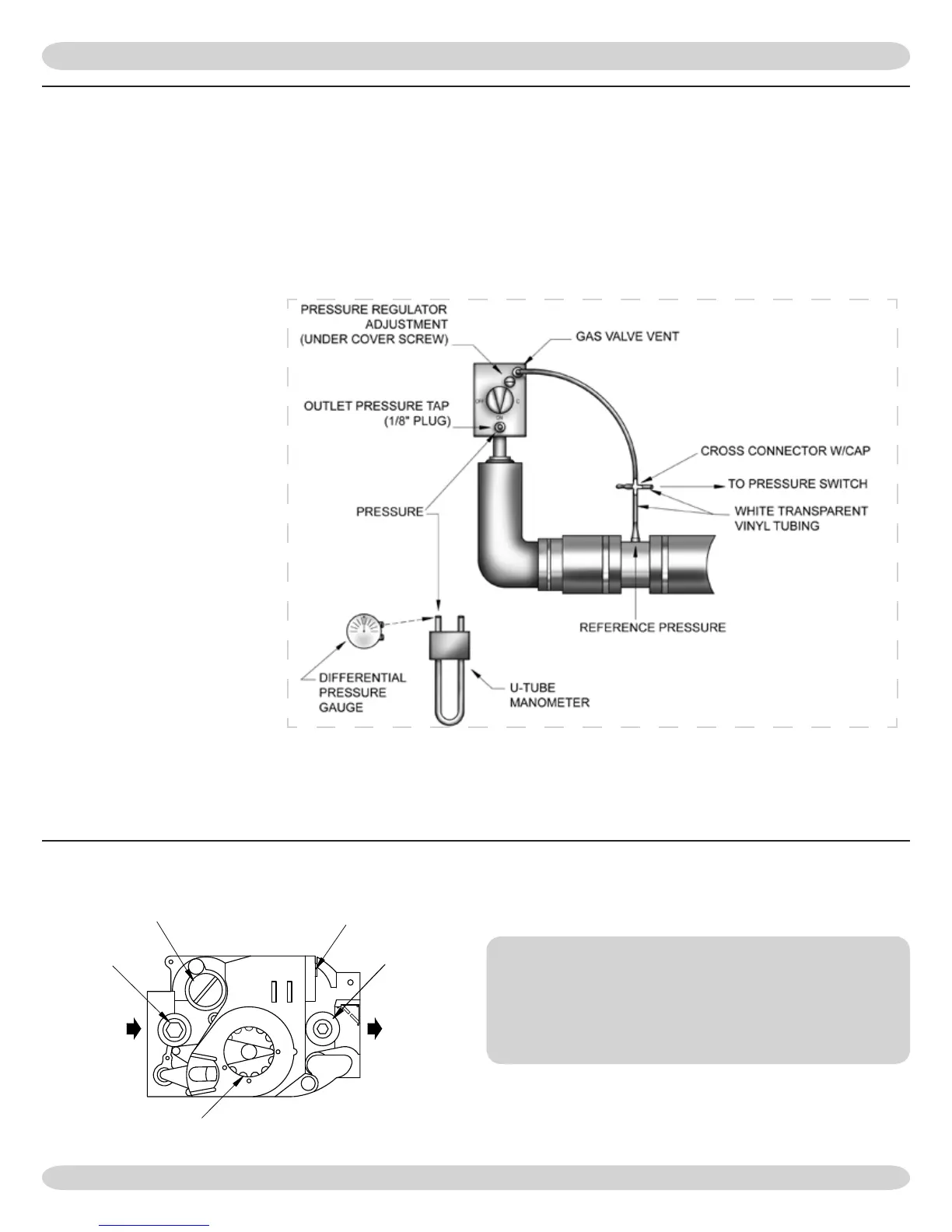
e following steps and diagram indicate the location of the
connection points required to measure the manifold pressure.
e manifold pressure may be measured using a U-Tube Ma-
nometer or a Dierential Pressure Gauge. e diagram shows
the connection of both measuring
devices. Only ONE DEVICE IS
REQUIRED to measure the mani-
fold pressure.
Remove the plug. Install the
appropriate barbed tting and
connect the pressure side line
from the U-Tube Manometer or
Dierential Pressure Gauge.
Refer to “CHECK OUT PROCE-
DURE AND ADJUSTMENTS”
in this manual when reading the
manifold pressure.
When measurement is completed,
disconnect the U-Tube Manome-
ter or Dierential Pressure Gauge.
Be sure to reinstall the ⅛” plug,
using appropriate pipe thread sealant approved for use with
natural and liqueed Petroleum gases.
OFF
ON
INLET
OUTLET
GAS CONTROL KNOB
PRESSURE REGULATOR
ADJUSTMENT (UNDER CAP SCREW)
INLET
PRESSURE
TA P
VR8205
WIRING TERMINALS (2)
OUTLET
PRESSURE
TA P
NOTE: Regulator cover screw must be installed at all
times unless adjusting manifold pressure. Firing rate and
manifold pressure must only be measured with cover screw
rmly installed.
 Loading...