Do you have a question about the Lennox KG Series and is the answer not in the manual?
Describes motorized damper operation with unit controllers and occupied signals.
Describes manual damper operation, manually set at installation.
Instructions for installing motorized dampers on LGH/LCH/KG/KC/KH units.
Instructions for installing motorized dampers on ZG/ZC/ZH units.
Wiring harness connections for LGH/LCH units.
Wiring harness connections for KG/KC/KH units.
Wiring harness connections for ZG/ZC/ZH units.
Installation steps for factory-installed motorized dampers on LGH/LCH/KG/KC/KH units.
Installation steps for motorized dampers on ZG/ZC/ZH units, focusing on the hood pivot bracket.
Steps to measure air temperatures and use Chart 1 to calculate outdoor air percentage.
Adjusting damper minimum position using Unit Controller menus for M2/M3 systems.
Adjusting damper stop for units without a controller using fixed increments.
Measuring static pressure differential for single blower speed operation.
Measuring static pressure differential for multiple blower speed operation.
Reading damper percentage open using controller or voltage measurement.
| Stages | Single |
|---|---|
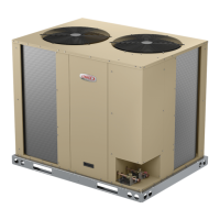
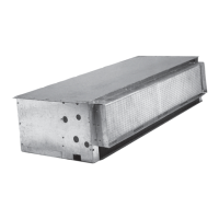
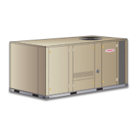
| Housing Material | Galvanized steel |
| Voltage | Varies by model |
| Speed Control | Variable |
| Sound Level | Varies by model |
| Application | Industrial and commercial heating, ventilating, and air conditioning (HVAC) systems |