Page 27
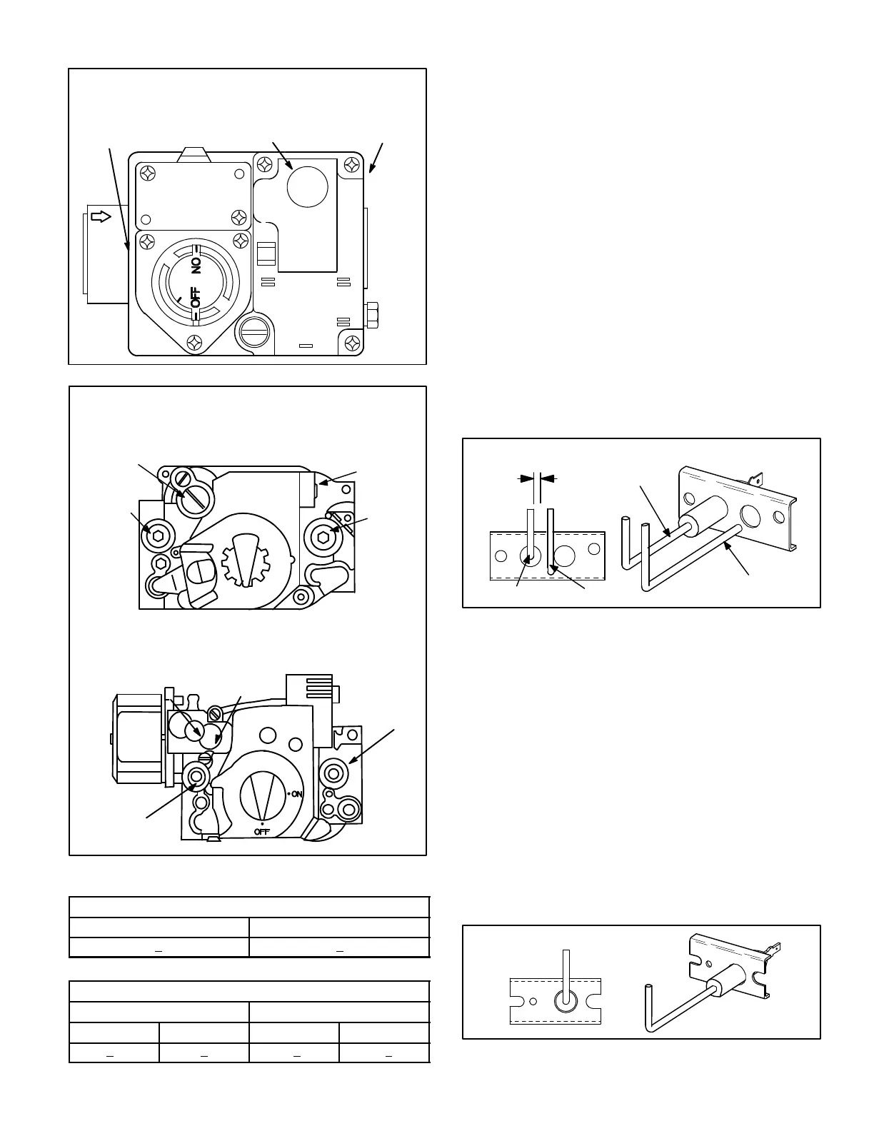
FIGURE 20
WHITE-RODGERS 36C76 GAS VALVE
TWO STAGE
D-1
GV-1
C-1
C2
GV-2
MANIFOLD
PRESSURE
TAP (SIDE)
STAGE 2 MANUAL MANIFOLD
PRESSURE ADJUSTMENT
SCREW UNDER CAP
INLET
PRESSURE
TAP (SIDE)
GAS VALVE SHOWN
IN “OFF” POSITION
GAS VALVE SHOWN
IN “OFF” POSITION
FIGURE 21
HONEYWELL VR8205 GAS VALVE
SINGLE STAGE
ON
OFF
PRESSURE
REGULATOR
INLET
PRESSURE
TAP
WIRING
TERMINALS
LOW FIRE
ADJUSTMENT
HIGH FIRE
ADJUSTMENT
INLET
PRESSURE
TAP
MANIFOLD
PRESSURE
TAP
HONEYWELL VR8305/VR8205 GAS VALVE
TWO STAGE
MANIFOLD
PRESSURE
TAP
GAS VALVE SHOWN
IN “OFF” POSITION
GAS VALVE SHOWN
IN “OFF” POSITION
TABLE 5
SINGLE STAGE GAS VALVE FACTORY SETTING
Natural (inlet-5.5” to 10.5”) L.P (inlet-11.0” to 13.0”)
3.5” + 0.3” 10.5” + 0.3”
TABLE 6
TWO STAGE GAS VALVE FACTORY SETTING
Natural (inlet-5.5” to 10.0”) L.P. (11.0” to 13.0”)
High Fire Low Fire High Fire Low Fire
3.7”+ 0.3” 1.9” + 0.2 10.5”+ 0.3 5.32” + 0.2
11-Spark Electrodes
An electrode assembly is used for ignition spark. The
electrode is mounted throughholes on the left-most end
of the burner support. The electrode tip protrudes into
theflame envelopeof the adjacent burner. The electrode as-
sembly is fastened to burner supports and canbe removedfor
service without removing any part of the burners.
During ignition, spark travels through the spark electrode (fig-
ure 22) and ignites the leftburner. Flame travels fromburner to
burner until all are lit.
The spark electrode is connected to the ignition control by a 8
mm silicone-insulated stranded high voltage wire. The wire
uses 1/4” (6.35 mm)female quick connect on the electrode
end and female spark plug-type terminal on the ignition control
end.
NOTE-IN ORDER TO MAXIMIZE SPARK ENERGY TO
ELECTRODE, HIGH VOLTAGE WIRE SHOULD TOUCH
UNIT CABINET AS LITTLE AS POSSIBLE.
GROUND
ELECTRODE
GROUNDELECTRODE
.125” ± .015”
(3.2 mm ± .4 mm)
FIGURE 22
12-Flame Sensors
Aflamesensor (figure23)islocated onthe right sideof the
burner support. The sensor is mounted through a hole in
the burner support and the tip protrudes into the flame enve-
lope of the right most burner. The sensor assembly is fastened
to burner supports and can be removed for service without re-
moving any part of the burners.
When flame is sensed by the flame sensor (indicated by
microamp signal through the flame) sparking stops imme-
diately. During operation, flame is sensed by current
passed along the ground electrode (located on the spark
electrode), through the flame and into the sensing elec-
trode. The ignition control allows the gas valve to stay
open as long as a flame signal (current passed through
the flame) is sensed.
SENSOR
FIGURE 23
 Loading...


