Do you have a question about the Lennox LCC360H4 and is the answer not in the manual?
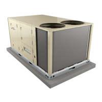
| Cooling Capacity | 36000 BTU/h |
|---|---|
| SEER Rating | 16 |
| Operating Voltage | 208/230V |
| Phase | 1 |
| Refrigerant | R-410A |
| Sound Level (Outdoor Unit) | 76 dB |
Contains critical safety warnings for installation and service.
Details cooling capacity, airflow, power, and EER.
Lists refrigerant charge amounts for R22 and R410A.
Lists compressor types and quantities for various models.
Specifies outdoor coil face area, tube diameter, rows, and fins.
Details outdoor fan motor horsepower, RPM, watts, and size.
Specifies indoor coil face area, tube diameter, rows, and fins.
Lists blower motor output and drive kit options.
Details input/output Btuh, thermal efficiency, and gas supply.
Explains derating for units installed at higher altitudes.
Lists electric heat capacities by voltage, kW, and steps.
Provides electrical data for compressors, fans, and blower motors.
Lists rated and locked rotor amps for compressors.
Lists disconnect types for electric heat control kits.
Lists amps for outdoor fan motors.
Details PEF horsepower and amps.
Details PEF horsepower and amps for high static.
Specifies GFI outlet rating and blower motor amps.
Provides minimum circuit ampacity for electric heat.
Provides maximum overcurrent protection for electric heat.
Details control modules and fuse blocks for electric heat.
Details terminal block options for electric heat.
Details pulley adjustment limits for blower speed control.
Lists specifications for CAV factory installed drive kits.
Lists specifications for high static PEF with VFD kits.
Lists specifications for VFD drive kits.
Details the compressor contactors and their function.
Describes the burner ignition controls for LGA units.
Details the blower motor overload relay.
Describes the scroll compressors used in the units.
Explains the function of high pressure switches.
Describes low ambient switches for low temperature operation.
Explains the function of low pressure switches.
Explains how to measure and adjust unit CFM.
Details CFM adjustment for CAV blowers.
Explains CFM adjustment for VAV blowers using VFD.
Details the procedure for adjusting belt tension.
Explains how to check belt tension and deflection.
Describes the burner ignition controls and their functions.
Explains the function of primary high temperature limits.
Describes the operation and types of gas valves.
Details secondary high temperature limits.
Describes combustion air prove switches for blower operation.
Introduces the IMC system and its boards.
Describes the main control module A55.
Details the compressor 2 control module A57.
Describes the compressor 3 & 4 control module A59.
Explains the gas valve control module A58.
Details the electric heat control module A60.
Describes the economizer control module A56.
Explains the primary high temperature limits for electric heat.
Details the redundant high temperature limit.
Details the steps for starting the unit in cooling mode.
Explains the importance of correct compressor and blower phasing.
Explains the approach method for checking refrigerant charge.
Critical safety instructions before lighting the unit.
Explains the operation of gas valves for startup.
Warning about electrical shock hazard during maintenance.
Instructions for operating gas valves for startup.
Procedure for initiating safety or emergency shutdown.
Procedure for testing gas supply pressure.
Procedure for checking and adjusting manifold pressure.
Steps to check for proper gas flow to burners.
Explains the supply air variable frequency drive.
Details the sequence for first stage cooling activation.
Details the sequence for second stage cooling activation.
Explains how electric heat sections operate.
Details the sequence for first stage heating activation.
Details the sequence for second stage heating activation.