Page 36
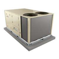
CLEAR
COVER
(SHOWN
CLOSED)
STOP
BUTTON
(RED)
RED TEST
BUTTON
(Push To Test)
AMP SETTING
CONTROL
(BLUE DIAL)
TRIP
INDICATION
WINDOW
LINE VOLTAGE IN
AMP SETTING
POINTER
BLUE RESET SCREW
(Shown in AUTO position as
shipped from the factory)
LOAD VOLTAGE OUT
DETAIL SHOWING RESET BUTTON
ADJUSTED TO MANUAL POSITION
Lift clear cover and turn adjustment screw
counterclockwise. Reset screw will pop out
when pointer is in M (manual position). Close
cover to lock reset screw into position.
TELEMECANIQUE OVERLOAD RELAY
Lift clear cover to adjust relay amp setting according to value given on the blower motor nameplate.
Proper relay amp setting equals motor nameplate FLA X service factor of 1.15 X .95.
Cover must also be lifted to adjust control mode from automatic reset to manual reset (see detail
above) and to test the control.
Control must be in the manual reset mode to perform a test. Use a pointed object to press the small
red test button. A yellow marker should appear in the trip indication window to the right of the amp
setting control. Press the blue reset screw to reset the relay.
The red STOP button opens the normally closed contacts which power the blower motor. This button
stops blower motor operation as long as it is pressed in.
FIGURE 8
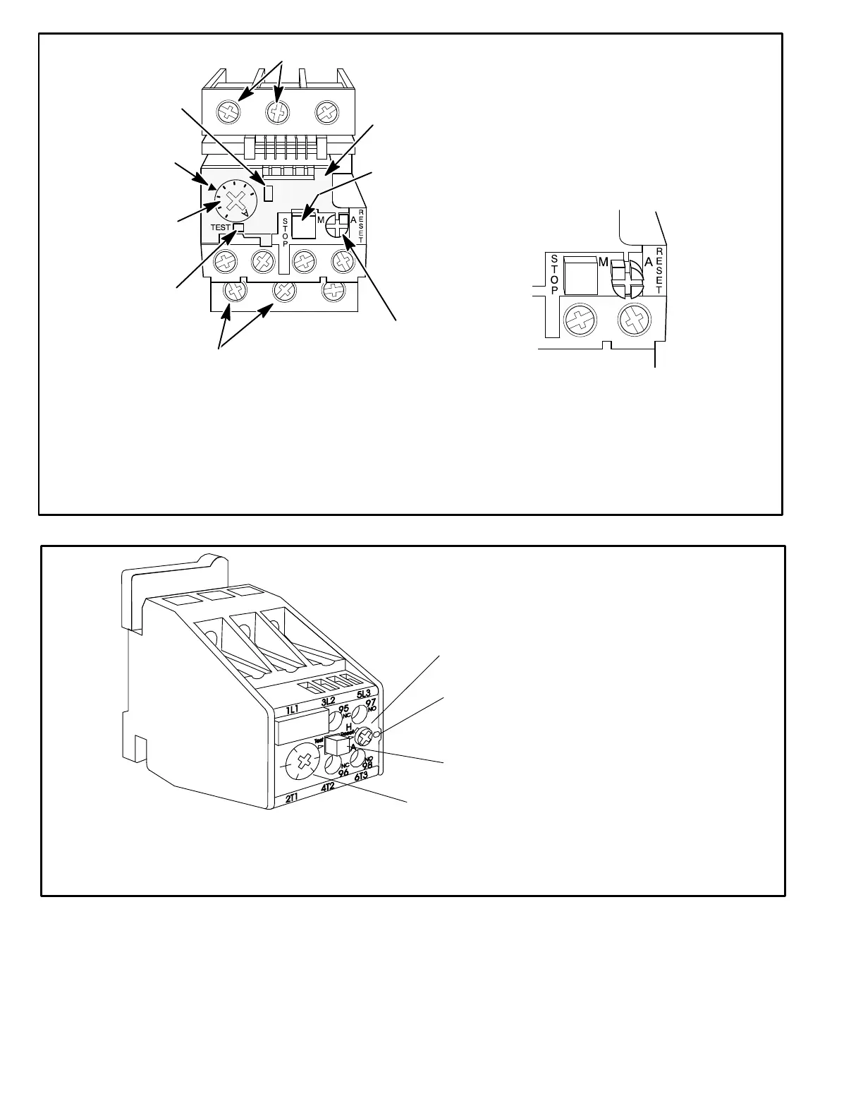
SIEMENS OVERLOAD RELAY
Adjust relay amp setting according to value given on the blower motor nameplate. Proper relay amp
setting equals motor nameplate FLA X service factor of 1.15 X .95.
Use small slotted screwdriver to adjust control mode from automatic reset (A) to manual reset (H).
Control must be in the manual reset mode (H) to perform a test. Press the red test button. Green trip
indicator should pop out. Press the blue reset screw to reset the relay.
BLUE RESET BUTTON IN
FACTORY‐SET AUTO MODE
(Turn clockwise to H for man
ual reset)
GREEN TRIP INDICATOR
(Flush with surface -- not tripped;
Above surface -- tripped)
AMP ADJUSTMENT DIAL
RED TEST BUTTON
FIGURE 9
 Loading...