Page 66
Caution - Units not equipped with a VFD will be set to Set
tings > Control > MSAV VFD Bypass > None. The blower
motor could be damaged and/or result in product or proper
ty damage if the setting is changed to automatic or manual.
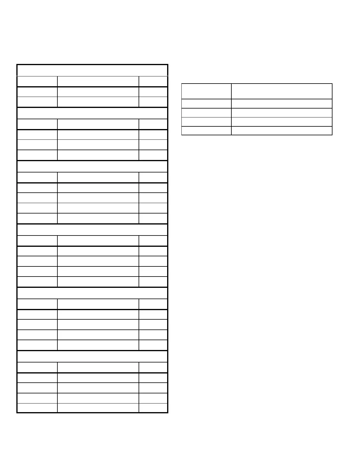
TABLE 27
MINIMUM AND MAXIMUM CFM
092H, 102H, 120H, 150S, 150H
Gas Heat Minimum CFM
Unit Gas Heat Size Airflow CFM
LGH092-150 Std. , Med. 2225
LGH092-150 High 2550
Electric Heat Minimum CFM
Unit Heat Size (kW) Airflow CFM
LCH092-102 0 2800
LCH092-150 7.5, 15, 22.5, 30, 45 2800
LCH120-150 0, 60 4000
Cooling Minimum CFM - 220* CFM/ton
Unit Blower Speed Airflow CFM
LGH/LCH092 Low 1650
LGH/LCH102 Low 1870
LGH/LCH120 Low 2200
LGH/LCH150 Low 2750
Cooling Minimum CFM - 280* CFM/ton
Unit Blower Speed Airflow CFM
LGH/LCH092 High 2100
LGH/LCH102 High 2380
LGH/LCH120 High 2800
LGH/LCH150 High 3500
Smoke and Ventilation Minimum CFM - 150 CFM/ton
Unit Not Applicable Airflow CFM
LGH/LCH092 NA 1125
LGH/LCH102 NA 1275
LGH/LCH120 NA 1500
LGH/LCH150 NA 1875
Heating and Cooling Maximum CFM - 480 CFM/ton
Unit Blower Speed Airflow CFM
LGH/LCH092 High 3600
LGH/LCH102 High 4080
LGH/LCH120 High 4800
LGH/LCH150 High 6000
*Refer to table 29 for ultra high efficiency unit minimum
CFM / ton. Ultra high efficiency units are equipped with tan
dem compressors which allow lower minimum airflow.
VIII-Direct Drive Supply Air Inverter
If a test and balance contractor has not commissioned the
unit, use this section to set supply air CFM.
A-Set Blower Speed
1 Use table 28 to fill in field-provided, design specified
blower CFM.
TABLE 28
Blower CFM Design Specifications
Blower Speed
Design
Specified CFM
Heating
Cooling High
Cooling Low
Ventilation
2 Use the following menu to enter the blower design
specified CFM into the Unit Controller. Don't press
“SAVE” until all CFM are entered. Make sure blower
CFM is within limitations shown in table 29. Refer to the
Unit Controller manual provided with unit.
SETUP > TEST & BALANCE > BLOWER
3 Once all four speeds are entered, the target (highest of
the heating and cooling settings) CFM and default
RPM will be displayed.
Note - When units are not equipped with heat, the Blower
Heat speed will not be displayed. Blower Cooling High will
be the first blower speed to appear.
4 Measure the static pressure as shown in the Blower
Start-Up section. Use the static pressure, target CFM
and blower tables to determine the RPM needed. Val
ues in the blower table reflect the static pressures tak
en in locations shown in figure 17.
5 Enter the RPM and repeat the previous step until the
design CFM is reached.
6 Press SAVE followed by MAIN MENU.
Note - Once the CFM settings are saved, the Unit Controller
will set all other blower CFM.
 Loading...