Page 67
B-Set Damper Minimum Position
To maintain required minimum ventilation air volumes when
the unit is in the occupied mode, two minimum damper posi
tions must be set. The Unit Controller will open the dampers
to “Min OCP Blwr Low” when blower CFM is BELOW a “mid
point” CFM. The Unit Controller will open the damper to “Min
OCP Blwr High” when blower CFM is at or ABOVE the “mid
point” CFM.
The Unit Controller will calculate the “midpoint” CFM.
Set Minimum Position 1
Use the following menu in the Unit Controller to set “Min
OCP Blwr Low” for the blower CFM below the “midpoint”
CFM. When navigating into this menu, the Unit Controller
will bring on the corresponding blower speed and allow
damper position adjustment.
SETTINGS > RTU Options > EDIT PARAMETER > ENTER
DATA ID - 9 > MIN DAMPER LOW BLOWER = X.X %
Measure the intake air CFM. If the CFM is lower than the
design specified CFM for ventilation air, use the Unit Con
troller to increase the damper percent open. If the CFM is
higher than specified, decrease the damper percent open.
Note - Intake air CFM can also be determined using the out
door air temperature, return air temperature and mixed air
temperature. Refer to the economizer or outdoor air
damper installation instructions.
Set Minimum Position 2
Use the same menu in the Unit Controller to set “Min OCP
Blwr High” for the blower CFM above the “midpoint” CFM.
When navigating into this menu, the Unit Controller will
bring on the corresponding blower speed and allow damper
position adjustment.
SETTINGS > RTU OPTIONS > DAMPER > MIN
DAMPER POSITION BLOWER ON HIGH = X.X %
Measure the intake air CFM. If the CFM is lower than the
design specified CFM for ventilation air, use the Unit Con
troller to increase the damper percent open. If the CFM is
higher than specified, decrease the damper percent open.
Note - Intake air CFM can also be determined using the out
door air temperature, return air temperature and mixed air
temperature. Refer to the economizer or outdoor air
damper installation instructions.
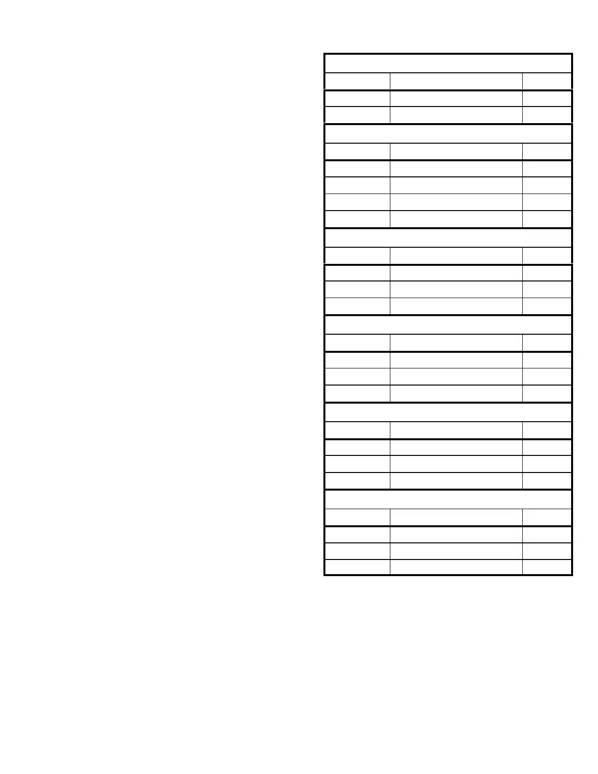
TABLE 29
MINIMUM AND MAXIMUM CFM
094U4E, 122U4E, 152U4E
Gas Heat Minimum CFM
Unit Gas Heat Size Airflow CFM*
LGH094-152 Std. , Med. 2225
LGH094-152 High 2550
Electric Heat Minimum CFM
Unit Heat Size (kW) Airflow CFM
LCH094 7.5 1750
LCH094 0, 15, 22.5, 30, 45 2750
LCH122, 152 15, 22.5, 30, 45 2750
LCH122, 152 0, 60 3500
Cooling Low Minimum CFM - 160 CFM/ton
Unit Blower Speed Airflow CFM
LGH/LCH094 Low 1200
LGH/LCH122 Low 1600
LGH/LCH152 Low 2000
Cooling High Minimum CFM - 220 CFM/ton
Unit Blower Speed Airflow CFM
LGH/LCH094 High 1650
LGH/LCH122 High 2200
LGH/LCH152 High 2750
Smoke and Ventilation Minimum CFM - 150 CFM/ton
Unit Not Applicable Airflow CFM
LGH/LCH094 NA 1125
LGH/LCH122 NA 1500
LGH/LCH152 NA 1875
Heating and Cooling Maximum CFM - 480 CFM/ton
Unit Blower Speed Airflow CFM
LGH/LCH094 High 3600
LGH/LCH122 High 4800
LGH/LCH152 High 6000
*Rounded to nearest 25 CFM.
 Loading...