Page 20
9-Power Exhaust Relay K65 & K231 (PED
units)
Power exhaust relays K65 and K231 are N.O. DPDT relays
with a 24VAC coil. The relay are used in units equipped with
the optional power exhaust dampers. K65 and K231 are
energized by the A55 Unit Controller, after the economizer
dampers reach 50% open (adjustable in ECTO). When K65
closes, exhaust fan B10 is energized and when K231 clos
es B11 is energized.
10-Variable Frequency Drive A96 (optional)
Staged-Blower units are equipped with a VFD which alters
the supply power frequency and voltage to the blower mo
tor. Blower speed is staged depending on the compressor
stages, heating demand, ventilation demand, or smoke
alarm. The amount of airflow for each stage is preset from
the factory. Airflow can be adjusted by changing ECTO pa
rameters in the A55 Unit Controller. The VFD is located be
low the Unit Controller.
11-VFD Power To Motor Contactor K202
(optional)
Contactor is used in Staged-Blower units equipped with a
VFD bypass option. The three‐pole 40 amp contactor with a
24VAC coil is energized by the A55 Unit Controller. K202 al
lows power from the VFD to the B3 blower motor in response
to blower demand.
12-Inverter Start Forward Rotation Relay K203
(optional)
Relay is used in optional Staged-Blower units and is a
three-pole double-throw relay with a 24VAC coil. K203 is
energized by the A55 Unit Controller and provides input to
the A96 VFD to start blower forward rotation. K203 also de-
energizes K3 allowing A96 to control B3 blower.
13-Unit Controller A55
The Unit Controller provides all unit control functions, unit
status information, unit diagnostics, programmable pa
rameters and USB verification and profile sharing. Refer
to the Unit Controller guide provided with the unit. Thermo
stat wires are connected to J297 on the Unit Controller.
14-Compressor 3 & 4 Controller A59 & A178
The compressor 3 & 4 control module A59 controls two ad
ditional compressor stages. A59 includes all inputs and
outputs required for compressor and fan control, compres
sor stage diagnostics and low ambient control.
The M3 unit controller is only compatible with L-Connection
sensors provided with the unit or purchased separately as
specified in the Product Specification. Tables 1 through 4
show thermistor and pressure transducer readings.
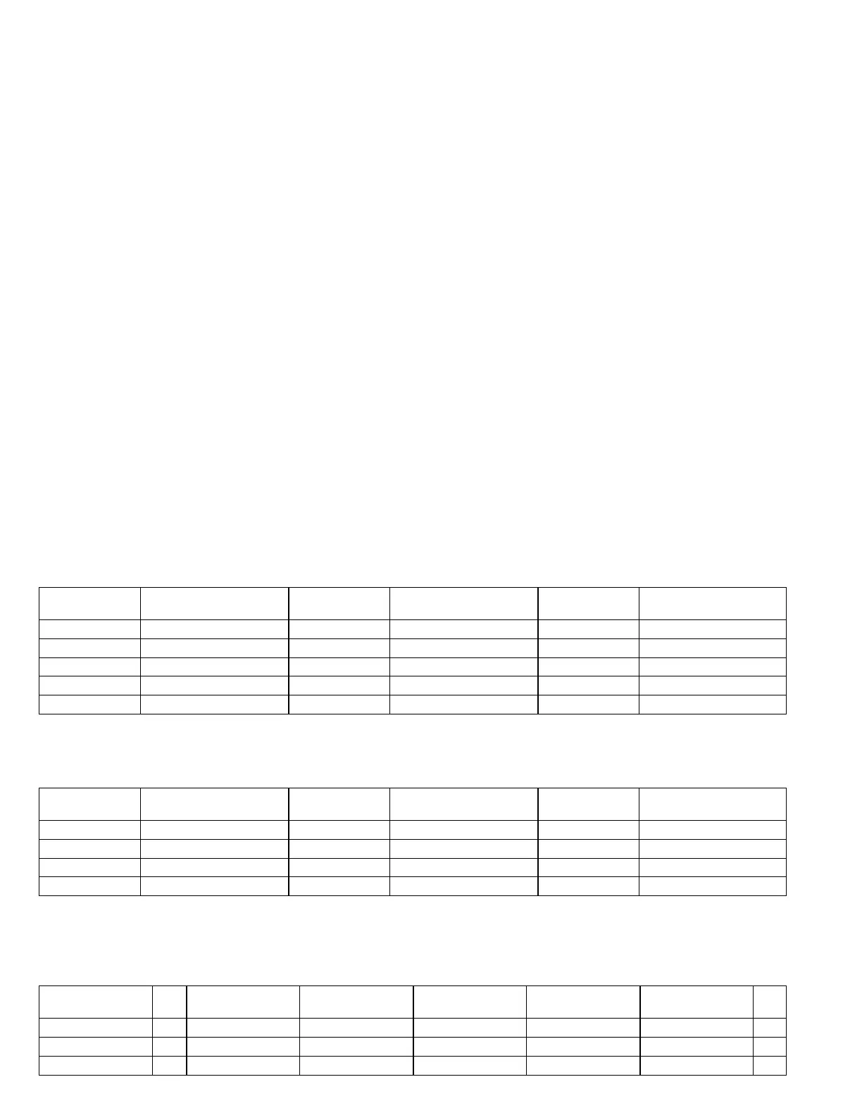
Temperature Sensors
The return air (RT16) and discharge air (RT6) duct probes
and the outdoor air (RT17) are all two wire thermistors. The
resistance vs. temperature table is shown below:
Table 1
Resistance vs. Temperature
Temp. °F (°C) Resistance +/-2%
Temperature °F
(°C)
Resistance +/-2% Temp. °F (°C) Resistance +/-2%
-40 (-40) 335,671 40 (4.4) 26,106 90 (32.2) 7,332
-20 (-28.9) 164,959 50 (10) 19,904 100 (37.8) 5,826
0 (-17.8) 85,323 60 (15.6) 15,313 120 (48.9) 3,756
20 (-6.7) 46,218 70 (21.1) 11,884 130 (54.4) 3,047
30 (-1.1) 34,566 80 (26.7) 9,298
Room Sensors
Room sensor (A2) is a two-wire thermistor with 1k series resistor.
Table 2
Two-Wire Thermistor
Temp. °F (°C) Resistance +/-2%
Temperature °F
(°C)
Resistance +/-2% Temp. °F (°C) Resistance +/-2%
40 (4.4) 27,102 60 (15.6) 16,313 80 (26.7) 10,299
45 (7.2) 23,764 65 (18.3) 14,474 85 (29.4) 9,249
50 (10) 20,898 70 (21.1) 12,882 90 (32.2) 8,529
55 (12.8) 18,433 75 (23.9) 11,498
Carbon Dioxide Sensor
The indoor carbon dioxide sensor (A63) is an analog sensor with a 0-10VDC output over a carbon dioxide range of 0-2000
ppm as shown in the following table. The sensor is powered with 24VAC.
Table 3
Carbon Dioxide Range
Carbon Dioxide
PPM
DC
V
Carbon Dioxide
PPM
DC Voltage
Carbon Dioxide
PPM
DC Voltage
Carbon Dioxide
PPM
DC
V
0 0 600 3 1200 6 1800 9
200 1 800 4 1400 7 2000 10
400 2 1000 5 1600 8
 Loading...

