Page 36
VI-ACCESSORIES
The accessories section describes the application of most of
the optional accessories which can be factory or field installed
to the LCM units.
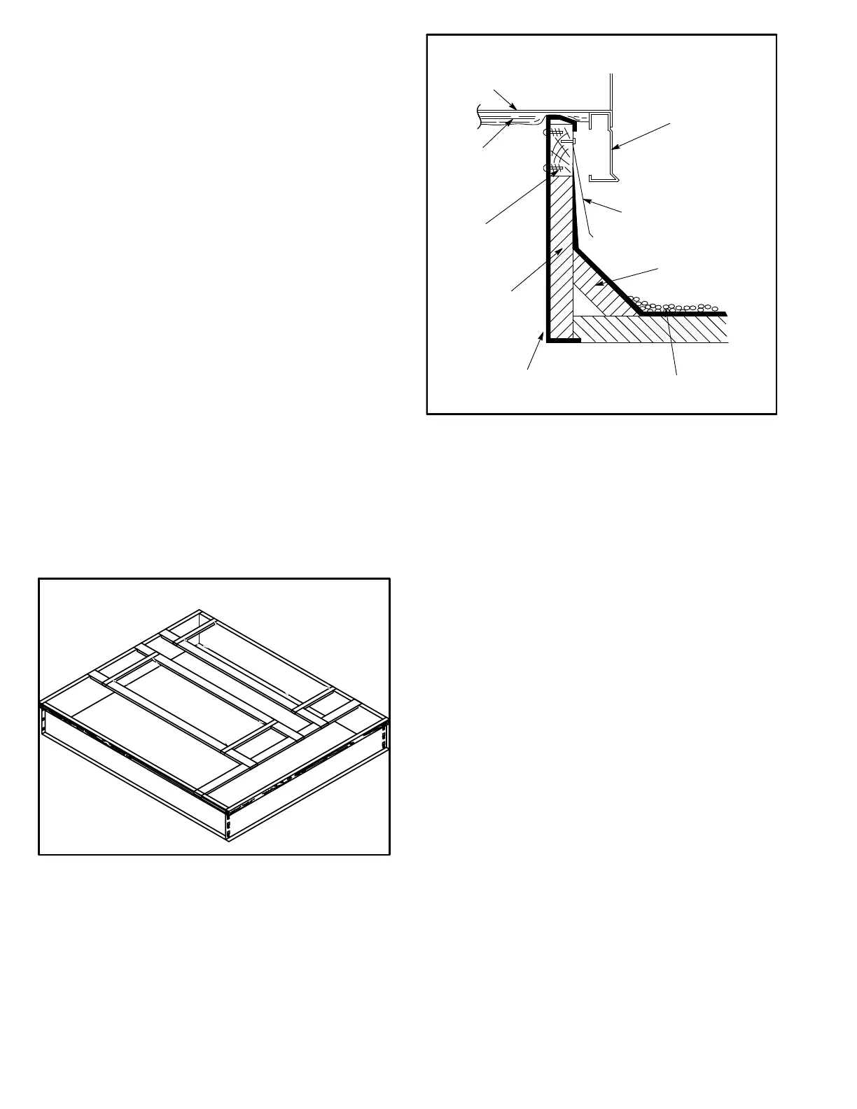
A-Roof Curbs
When installing the LCM units on a combustible surface
for downflow discharge applications, the hybrid
C1CURB70C-1 8-in height, C1CURB71C-1 14-in height,
C1CURB72C-01 18-in height and C1CURB73C-1 24-in
roof mounting frame is used. The assembled hybribd
mounting frame is shown in figure 17. Refer to the roof
mounting frame installation instructions for details of proper
assembly and mounting. The roof mounting frame MUST
be squared to the roof and level before mounting. Plenum
system MUST be installed before the unit is set on the
mounting frame. Typical roof curbing and flashing is shown
in figure 18. Refer to the roof mounting frame installation in
structions for proper plenum construction and attachment.
For horizontal discharge applications, use the standard
C1URB14C-1 26-in or C1CURB16C-1 37‐in height roof
mounting frame. This frame converts unit from down‐flow
to horizontal air flow. The 37 inch horizontal frame meets
National Roofing Code requirements. The roof mounting
frames are recommended in all other applications but not
required. If the LCM units are not mounted on a flat (roof)
surface, they MUST be supported under all edges and un
der the middle of the unit to prevent sagging. The units
MUST be mounted level within 1/16” per linear foot or
5mm per meter in any direction.
FIGURE 17
ASSEMBLED HYBRIDROOF CURB
FIGURE 18
ROOF
MOUNTING FRAME
(Extends around entire
perimeter of unit)
FIBERGLASS
INSULATION
(Furnished)
COUNTER FLASHING
(Field Supplied)
UNIT BASE
BOTTOM
RIGID INSULATION
(Field Supplied)
ROOFING
MATERIAL
CANT STRIP
(Field Supplied)
NAILER STRIP
(Furnished)
UNIT BASE
RAIL
TYPICAL FLASHING DETAIL
B-Transitions
Optional supply/return transitions C1DIFF33C-1 and
C1DIFF34C-1 are available for use with LCM series units
utilizing optional C1CURB roof curbs. Transition must be
installed in the roof curb before mounting the unit to the
frame. Refer to the manufacturer's instructions included
with the transition for detailed installation procedures.
C-C1DAMP10 & E1DAMP20 Outdoor Air
Dampers
C1DAMP10C and E1DAMP20C (figure 19) consist of a set
of dampers which may be manually or motor operated to al
low up to 25 percent outside air into the system at all times
(see figure 19). Either air damper can be installed in LCM
units. Washable filter supplied with the outdoor air dampers
can be cleaned with water and a mild detergent. It should be
sprayed with Filter Handicoater when dry prior to reinstalla
tion. Filter Handicoater is R.P. Products coating no. 418 and
is available as Part No. P-8-5069.
 Loading...

